Realtime live display of the information the electronic control unit of the selected vehicle system is currently deriving from its input sensors.
FUELLING
- Loop status: This confirms the current status of the GEMS loop tuning system and tells if it is currently active and working correctly. Options are:
- OPEN NOT YET SATISFIED CONDITIONS: The engine is not running or is still too cold to use the feedback from the sensors so when there is nothing wrong, the system is open loop.
- CLOSED USING O2 SENSORS NORMALLY: Proper operation with no faults.
- OPEN DUE TO DRIVING CONDITIONS: The system has been using the sensors and there are no problems, but it has decided not to use them at the moment as the feedback is not required for correction.
- OPEN DUE TO A DETECTED FAULT: There is a fault with the sensor and the system has reverted to using the pure map without the aid of closed loop correction.
- CLOSED BUT AN O2 SENSOR IS FAULTY: This can only happen in vehicles fitted with 2 sensors per bank (NAS). Although the system knows one of the sensors is faulty it can switch to using the other one to give closed loop fuel correction.
- Pre cat Oxygen Sensor: This is the returning voltage value from the odd/even banks front (pre-catalyst) Oxygen sensor, which under normal operation (closed loop) should switch between very low values (near zero volts) when the mixture is too rich and very high values (near 5.0 volts) when the mixture is too weak. This switching may pause for brief periods, which is normal. Some markets (mainly Australia) had no sensors fitted and work entirely open loop.
- Post cat Oxygen Sensor: This is the returning voltage value from the even banks rear (post-catalyst) Oxygen sensor, which under normal operation (closed loop) should switch between very low values (near zero volts) when the mixture is too rich and very high values (near 5.0 volts) when the mixture is too weak. This switching may pause for brief periods, which is normal. Sensors are only fitted after the catalyst in some countries like North America (NAS) and are used mainly for confirming the correct operation of the catalytic converter although this sensor can be used in the event of failure of the main pre-catalyst sensor.
- Fuel trim long term: The percentage of alteration from the map value that the system is applying, to compensate for engine temperature, air temperature, fuel temperature, current engine load and other related conditions.
- Fuel trim short term: The percentage of alteration from the map value that the system is applying, to momentarily compensate for feedback information, acceleration and other load conditions.
OTHER
- Fuel temperature: This is the value obtained from the fuel temperature sensor, which is located on the metal fuel rail in-between, the cylinder heads. When the engine has been running and is then stood for a short time, heat escaping from the engine can super heat the fuel trapped in the fuel rail, meaning that when restarting an already hot engine, problems can arise (hot starting problems). Having the fuel temperature information means that the GEMS can compensate for this by increasing the injector opening (pulse) period when the fuel temperature is high. This sensor is treated as fail-safe by GEMS with the system substituting a value of 40 degrees centigrade upon detection of its failure.
- Fuel level: This is the measured voltage indicating current fuel tank level, which is used by GEMS for internal evaporative emission tests. The value is inverted, meaning the closer to the maximum of 5 volts it becomes, the emptier the fuel tank is and the closer to the minimum of zero the value becomes, the fuller the fuel tank.
- Oxygen configuration: This is the numerical value obtained from GEMS, which denotes it's expected oxygen sensor layout. Options are:
- 00: No oxygen sensors are fitted and GEMS runs completely open loop.
- 11: The most common arrangement with 1 sensor in each cylinder bank mounted upstream of the catalytic converters (where fitted).
- 33: This configuration is usually used in countries that have stricter emission control regulations (e.g. North America). Besides having the two normal sensors as per 11, it also has two more sensors each being mounted downstream of the catalytic converters in each cylinder bank. This not only gives GEMS the ability to monitor the efficiency of the catalytic converters but also provides a fail-safe in the event of one of the sensors going faulty.
- Pre Cat Oxygen Sensor Heater: This value shows the returning voltage from the front pair of (pre-catalyst) oxygen sensor heaters, which corresponds to their current heat output. The value should fluctuate as the GEMS switches or pulses the Heaters power on and off to regulate the temperature. If the value remains fixed in normal operating conditions one of the heaters may be faulty.
- Post Cat Oxygen Sensor Heater: This value shows the returning voltage from the rear pair of (post-catalyst) oxygen sensor heaters (when fitted), which corresponds to their current heat output. The value should fluctuate as the GEMS switches or pulses the Heaters power on and off to regulate the temperature. If the value remains fixed in normal operating conditions one of the heaters may be faulty.
- Adaptive FMFR: The Adaptive Fuel Mass Flow Rate (FMFR) is learnt by the system over a period of time and is added to the normal fuel rate to compensate for manufacturing tolerances between fuelling components. The extremes of tolerance that GEMS allows for is + 0.625 to -0.625. After which it will log a fault in its fault code memory.
AIR AND IDLE
- Current throttle position: The value returned from the Throttle position potentiometer, which is located on the side of the Throttle body. During normal idling this should be around 0.5 to 0.65 volts, increasing towards 5.0 volts as the throttle pedal is pressed and the engine approaches 5500 RPM. This input signal is fail-safe, as failure in the closed position results in the GEMS limiting the engine RPM to 1740, above which is restricted by the over run fuel cut-off being applied.
- Stored throttle position: This Adaptive value is stored by the GEMS so it knows when the vehicle is at idle. If any adjustments are made which result in the stored value being lower than the current throttle position with the throttle properly closed and the vehicle at idle, it is possible to have the Gems either re-learn its new value by re-setting all ECU Adaptations or the value can be manually edited in the Settings section.
- Adaptive air flow value: The Adaptive Air Mass Flow Rate (AMFR) is learnt by the system over a period of time and is added to the normal air rate to compensate for manufacturing tolerances between airflow components. The extremes of tolerance that GEMS allows for is + 5.5 KG/HR to -5.5 KG/HR. after which it will log a fault in its fault code memory.
- Current air flow: This is the current reading taken from the Air Flow Meter. It should be around middle 20's at idle rising steadily with engine RPM until around 200 KG/HR at 5500 RPM.
- Intake air temperature: The current value read from the Temperature sensor, which is mounted in the side of the air filter box. Used by GEMS to compensate for climatic variances. The sensor is fail-safe with GEMS substituting a value of 50 degrees centigrade in the event of sensor failure.
- Air flow sensor voltage: This value is the pure voltage reading taken from the Air Flow Meter that GEMS uses to work out the flow rate in Kg/Hr. At idle, the value should be around 20 - 25Kg/Hr.
- Secondary air status: Commanded Secondary air Status. Options are:
- 1: Upstream of first catalytic converter.
- 2: Downstream of first catalytic converter inlet.
- 4: Atmosphere / off.
Any other value is invalid.
- Current run line position: This value is the number of steps for the current run line position.
- Long term adaptive idle: This is the value that the GEMS learns over a period of time to take into account manufacturers' tolerances on components which affect overall idle speed. It can be reset, forcing the GEMS to re-learn this value or it can be manually altered in the settings section.
- Short term adaptive idle: This is the value that the GEMS uses to regulate the current idle speed to take into account current engine load, temperature, etc. It can be manually altered in the settings section.
- Idle reference speed: This is the target idle speed in RPM that the GEMS uses as a reference when self adjusting the idle speed. This is not settable and is pre-set into the ECU.
- Idle air control valve position: The Idle Air Control Valve (IACV) has a stepper motor mounted on it, which controls its position in steps thereby regulating the air flow at idle and thus the idle speed. The position of this stepper motor is adjustable and should be such that a warm engine at normal idle should cause the stepper motor to be at between 15 and 30 steps. The value can be between zero (closed) and 200 (open).
- Engine speed RPM: The current Engine RPM.
- Current gearbox retard: This is derived from a signal sent by the Automatic Gearbox (where fitted) and is used to inform the GEMS of gear changes, torque and load so that GEMS may retard the ignition accordingly, producing smoother gear changes. At idle this should be 17% increasing towards 100% as and when ignition retarding is required.
- Calculated load value: This is an internal value where the GEMS keeps a track on the load that the engine is under it is used in internal fuelling calculations.
- Current gearbox status: This status is used by the GEMS so that idle may be better maintained as the Automatic Gearbox load is applied to the engine.
ENGINE AND OTHERS
- Coolant temperature: The value obtained from the engines coolant temperature sensor.
- Battery voltage: The current state of the battery at the GEMS ECU. Some GEMS ECUS built around 1996 were faulty and did not correctly report the voltage, instead supplying a fixed signal which incorrectly indicates 16 volts.
- Road speed: The road speed as supplied to the GEMS ECU from the ABS ECU.
- Air conditioning request: When the A/C button is pressed an active low signal is output to the GEMS ECU (The Request). This then looks at factors like engine temperature, load, current acceleration etc., and when these conditions allow, grant Air conditioning. This involves it engaging the clutch to drive the Air Conditioning pump, altering its internal fuelling to compensate for the load imposed by the pump, managing along with the Hevac the Condenser fans, and also telling the Hevac that Air Conditioning has been Granted. This shows the current status of the request line from the Hevac ECU.
- Front screen load: This is an input which tells the GEMS ECU that the heated front windscreen is being switched on so that it can compensate for the heavier electrical load on the alternator.
- Ignition switch: The current ignition switch state as determined by GEMS.
- ABS volts: The ABS has the ability to inform the GEMS ECU that the vehicle is encountering unusually rugged terrain. Thus, should the GEMS think that it has had a engine misfire during such driving it can be persuaded not to falsely log a misfire fault in its fault code memory.
- Security learn: When the ignition is turned on, the BECM providing it is in receipt of a valid mobilisation code and is therefore not in an alarmed or immobilised state, sends a coded signal to the GEMS which the GEMS then compares against a mobilisation code it has stored in it. If the two codes compare OK the GEMS allows the engine to start. This forms the basis of the immobiliser. If the GEMS ECU, the BECM, or the lockset & key fob is replaced, or other data in the BECM is changed, it may be required for the GEMS to re-learn a new mobilisation code. This is done by putting the GEMS into Security learn mode whereby the next coded signal it receives is not compared, but is instead stored as the master copy. When security learn mode has been entered, the ignition has to be turned off and turned back on to trigger the BECM into sending the code. The GEMS will check the incoming code and should accept it; however, if there is an error, however slight in the codes makeup, the GEMS can reject it; in such a case there will be no valid code stored. This status indicates whether the system has a valid code stored or not and is only valid in the ignition cycle in which is learned.
- Security mobilised: This shows the status of the engine immobiliser built in to the GEMS.
- Xfer box volts: This signal is only valid for the North American specification (NAS) vehicles. It allows the Transfer box to signal to the GEMS situations which affect emissions.
- Ignition timing advance deg: An internal record of calculated timing advance applied by the GEMS.
|
 LUCAS GEMS - System Overview
 LUCAS GEMS - Known Fitments
 LUCAS GEMS - Physical Details
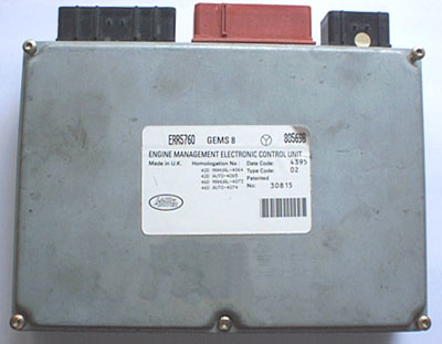
 LUCAS GEMS - Pin Outs
