Values, configuration settings, and other stored information which can be read from the ECU, edited and then rewritten back. Read settings can also be stored as a standard HTML page for reference. These pages can then later be re loaded and re written back to the ECU. Please note that some values may be read only due to the fact that they are supplied from the ECU’s ROM or are internally calculated.
Clicking on the settings link, it will open a page with two choices, "Settings and Information" and 'Coding Data". The first page contains information about Lucas 10 AS alarm, settings information, and gives the possibility to change different settings of the alarm.
The second page contains only coding data, and is to be used only to program a new or corrupt ECU.
SETTINGS AND INFORMATION
- Time Error: Both the alarm and the plip each have a timer in them which stays in synchronization and can be used as part of the correct key verification sequence every time the key is used. However it is possible for one of the timers to run marginally faster or slower than the other. Setting this value to yes allows the alarm to accept an error rate of up to 9 seconds in every hour between the two as a pass.
- Comms: This setting controls communications activity standby control.
- Interior Light: This setting controls the level of operation of the interior light.
- Low Battery: When set to ENABLED this configures the alarm to notify the user via the security LED that the plip has a low battery in accordance with the other settings which affect this function's operation. When set to NO the function is totally disabled.
- Low battery error: This configures the alarm to notify the user via the Security LED either on the first receipt of a key code in which the low battery flag is set or to wait until it has received a number of them in succession. The exact number is determined by the value stored in the LOW BAT COUNT box.
- Arm/disarm flash: These settings determine if the hazard lights will be used to indicate the arming or disarming of the alarm.
- Immobiliser type:: This option allows the verification and configuration of the 10AS alarm's immobiliser function to suit one of the fitted engine options. It is important to select the correct engine management type to ensure that the engine starts afterwards. There are 5 options which the immobiliser type can be set to:
- SPIDER This is used on vehicles which use an engine management which has no immobilize facility built in. It is basically an add on style immobiliser box which communicates with the alarm. The engine types that use the Smart Spider are 14CUX and non EGR Diesels. The spider has to learn a fixed code which is sent out from the 10AS alarm unit to mobilize and is instructed to re learn a code by using the SPIDER LEARN function found in the OTHER section.
- EDC This is selected to configure the alarms immobiliser for the EDC engine management. The alarm sends a code (the EDC code) to the EDC engine management control unit. This code can be read from the EDC control unit using the 'READ EDC CODE' function provided in the EDC diagnostic section. This code can then be entered into the EDC code box provided. Failure to enter the correct EDC code number will result in the vehicle not starting unless the EDC ECU is was programmed to non robust.
- DDS is selected to configure the alarm immobiliser for DDS. The alarm communicates with DDS control unit which is attached directly to the fuel pump and causes this to stop the engine from running. If either the alarm or DDS ECU have been replaced, the alarm and DDS have to be synchronised with each other to work correctly. This takes approximately 30 minutes and can be instigated by using the DDS LEARN function in the OTHER section.
- GEMS is selected to configure the alarm for GEMS engine management systems. The alarm communicates with GEMS ECU. Should the alarm or engine ECU be changed or the stored GEMS code, the relevant engine ECU will have to learn the new code using its learn function.
- TD5/MEMS This is selected to configure the alarms immobiliser for the TD5 or MEMS engine management system. The alarm communicates with the TD5 engine management control unit directly. Should the alarm or engine ECU be changed, the relevant engine ECU will have be to learn the new code using its learn function.
- MEMS failure indicator: The MEMS, upon receipt of a valid mobilise code, not only mobilises the engine but sends back a signal via its MIL circuit which indicates its change from immobilised to mobilised status. This setting instructs the alarm that the MEMS failed to mobilise.
- Arm disarm confirm: If the alarm is armed or disarmed twice in succession this setting will determine if the hazard lights are used to confirm the status of the alarm or not.
- Key disarm: This determines if the alarm can be disarmed by using the key in the lock after it was armed using the plip. The engine would also mobilise if KEY mobilise was set to ALLOWED.
- Mislock: In the event of a mislock, which is usually due to a door being open, the alarm will continue to activate the volumetric sensors if this setting is set to ENABLED, or it will omit them from the vehicle's protection if this setting is set to NO.
- CDL when arm: This determines if the central door locking will still operate when the alarm is armed.
- Time Synchronize: Both the alarm and the plip each have a timer in them which stays in synchronization and can be used as part of the correct key verification sequence every time the key is used. Setting this value to No turns off this function.
- Key mobilise: This determines if the alarm will mobilize the engine if it has been disarmed by using the key in the lock after it was armed using the remote plip. KEY DISARM would obviously have to be ALLOWED to prevent the alarm from being triggered.
- Cat overheat: The 10AS alarm had a function built into it to monitor temperature sensors on the Catalytic converters. This was no doubt to accommodate markets where it is a legal requirement to have a warning indicator in the event of failure of one of the two catalytic converter heaters. The Dynamic inputs screen shows the values derived from the Analogue to Digital converters which are connected to the two input pins reserved for this feature. And the CAT THRESHOLD setting marks the threshold point at which the security LED warning lamp would be illuminated if the system were activated. This setting turns on the Catalytic converter temperature warning system.
- Flash on alarm: This setting determines if the hazard lights will flash when the alarm has been triggered.
- Arm on lock: This setting configures the alarm to not set whenever the vehicle is locked using the plip or the key. Setting this to DISABLED effectively turns off all alarm protection although it does not affect the immobiliser. This can be disabled using the PLIP IMMOBILISE and KEY IMMOBILISE. Turning off all three literally turns the alarm ECU into a central locking controller only.
- Plip relock: When set to ENABLED the alarm will relock the CDL after a short time if the ignition has not been turned on after it was unlocked using the plip.
- Plip immobilise: This setting configures the alarm to not immobilize the vehicle whenever the vehicle is locked using the plip. Setting this to NO effectively turns off engine immobilization protection when the plip is used to arm the alarm although it does not affect the immobilization when the key is used or the alarm itself . This can be disabled using the KEY IMMOBILISE and the ALARM ARMING. Turning off all three literally turns the alarm ECU into a central locking controller only.
- Resync on lock: When set to ENABLED the alarm and the key will synchronize to each other whenever the vehicle is locked.
- Resync on arm: When set to ENABLED the alarm and the key will synchronize to each other whenever the alarm is armed.
- Passive immobilise: This settings configures the alarm to automatically activate the immobiliser a certain period of time after the key is removed.
- Relock: This determines if the automatic arming with central door relocking function is ENABLED or DISABLED.
- Mislock noise: This setting determines if the alarm will issue a mislock noise if a mislock condition is detected.
- Vehicle type: This setting configures the alarm for operation in a Defender or a Discovery.
- Alarm sound: This setting determines if the horn will sound in a continuous tone or if it will be pulsed when the alarm has been triggered.
- Welcome light: This function decides if the interior light will come on automatically when the alarm is disarmed.
- Plip relock: When set to ENABLED the alarm will relock the CDL after a short time if the ignition has not been turned on after it was unlocked using the plip.
- Alarm serial number: This is the serial number of the alarm as printed on a label affixed to the lid.
- Plip presses for easy synchronization: This is the number of presses of the plip to allow an easy resynchronization.
- Plip presses for resynchronization: During a resynchronization of the plips, the plip has to be pressed this number of times.
- Plip presses for low battery: To rule out spurious errors the alarm must receive more than one consecutive transmission of a plip in which the low battery indication is set. This value is the number of successive transmissions to be received before the alarm activates the low battery indication via the security LED.
- Bad plip keycode allowance: This is the number of invalid plip codes the alarm will accept before triggering.
- Plip keycode: The plip code information uniquely identifies each key it is split in 4 parts. It is possible to obtain the number for any given key by learning it to the 10AS alarm and then reading this number from the alarms memory. Once you know what the number is for any given plip you can then simply type in its code into any alarm you wish to react to it.
- EKA code: This is a special Emergency Key Access code which can be entered into the alarm using either the door lock or in the case of the Defender the door ajar switch. Exact details of the procedure can be found in the vehicles handbook.
- EDC code: This is the code transmitted by the 10AS alarm unit when EDC is selected as the engine immobiliser option. It is vital to ensure that this code matches that of the EDC ECU. The code can be read from this in the settings function of the EDC section.
- EGR/DDS code: This is the code transmitted by the 10AS alarm unit when DDS is selected as the engine immobiliser option. It can have any value between 0 and 65535. Early alarms did not support the DDS immobiliser function and therefore do not have this value.
- GEMS code: This is the code transmitted by the 10AS alarm unit when GEMS is selected as the engine immobiliser option. It can have any value between 0 and 65535.
- TD5/MEMS code: This is the code transmitted by the 10AS alarm unit when TD5/MEMS is selected as the engine immobiliser option. It can have any value between 0 and 65535.
CODING DATA
- Coding Data 1-32: 32 blocks of programmable data stored in the ECU to control its functionality for specific variations of vehicle. There are a number of hexadecimal digits, each digit separated by a comma. Re-entered parameters should be entered in an identical format to that which is read. Changing this values can produce unknown alteration in the functionality of the ECU, damage the ECU or even damage your car.
|
 LUCAS 10AS ALARM - System Overview
 LUCAS 10AS ALARM - Known Fitments
 LUCAS 10AS ALARM - Physical Details
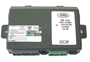
 LUCAS 10AS ALARM - Pin Outs