IPAC TYPE 2 (NGRR) - System Overview
Although the Face & design is specifically designed for the L322 Range Rover application, this unit is possibly the most flexible and adaptable that we have ever seen in respect of its configuration settings. It also has a built in diagnostic test and information retrieval capability accessible through the front buttons.
SM047 - IPAC TYPE 2 (NGRR) - System Help file
Version 1.29

IPAC TYPE 2 (NGRR) - Known Fitments
Vehicle makes, models and variants known or believed to be using this vehicle system, required diagnostic lead and degree of known compatibility.
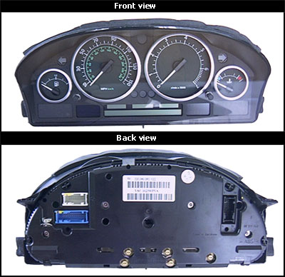
Vehicle Make Vehicle Model Vehicle Variant Diagnostic Lead
Land Rover Range Rover MK III ( L322) 2002 - Mid 2005 Black OBDII Lead/LD020/LD021

IPAC TYPE 2 (NGRR) - Physical Details

SM047 - IPAC TYPE 2 (NGRR) - Diagnostic Capabilities (Read Fault Codes)
Reads the fault code memory. The ECU can self detect up to 34 different problems with itself, its wiring and its associated sensors, storing the respective code if it detects any malfunction or reading outside of pre defined acceptable limits. Not all stored faults may cause the fault warning lamp to illuminate.

SM047 - IPAC TYPE 2 (NGRR) - Diagnostic Capabilities (Clear Fault Codes)
Clears the fault code memory.

SM047 - IPAC TYPE 2 (NGRR) - Diagnostic Capabilities (Settings)
Values, configuration settings, and other stored information which can be read from the ECU, edited and then rewritten back. Read settings can also be stored as a standard HTML page for reference. These pages can then later be re loaded and re written back to the ECU. Please note that some values may be read only due to the fact that they are supplied from the ECU’s ROM or are internally calculated.

  • Date of Build: The week and the year that the instruments pack was manufactured. The format for the date is ww/yyyy.
  • Hardware Number: The instrument pack's hardware number as shown by Test Function No 1. The ECU accepts a number between 0 and 99.
  • Change Index: The instrument pack's Change Index as shown by Test Function No 1. The ECU accepts a number between 0 and 99.
  • CAN Index: The instrument pack's CAN Index as shown by Test Function No 1. The ECU accepts a number between 0 and 99.
  • Bc Year: The year currently programmed into the board computer. This can be between 1997 and 2050.
  • Bc Code: The code currently programmed into the board computer and used for immobilisation function. This code can be any number between 0 and 9999.
  • Fuel Consumption Correction: The value as shown by Test No 20 which corrects the fuel consumption indicators. For more information see Test Function No 20. This can be a number between 750 and 1250.
  • Manufacturer Calibration Value: This is a calibration value used by the manufacturer. It is unique for each dashboard, it will remain the same and cannot be changed. New dashboards will have a new unique calibration value. This can be a number between 0 and 65535.
  • LCM to Ipac Vin Match: If the VIN Number in the lighting control module and the instrument pack do not match this will be set to NOT MATCHED.
  • Bc Code Function: Indicates if the board computer immobilisation code function is used or not.
  • Write Protect: This is a function not used in the Land Rover but can be used to protect certain blocks of the memory.
  • Information Channel: Denotes if CAN messages are used on this instrument pack and is set to By CAN as opposed to Other as is CAN Id Sent 2 and CAN ID Sent 3. Default for Range Rover usage is set to By CAN instead of disabled.
  • Programmed Flag 1: This flag is either programmed or not programmed. It is only NOT PROGRAMMED on a new dashboard. It needs to be programmed.
  • Programmed Flag 2: This flag is either programmed or not programmed. It is only NOT PROGRAMMED on a new dashboard. It needs to be programmed.
  • CAN Id Sent 2: This denotes part of the format of the CAN ID messages from the instrument pack.
  • CAN Id Sent 3: This denotes part of the format of the CAN ID messages from the instrument pack.
  • Gear Shift Data by CAN: This can be either CAN bus or other and denotes if the current gear selected information is given to the instrument pack by the CAN bus or other.
  • Fuel Consumption Data by CAN: This can be either CAN bus or other and denotes if the fuel consumption selected information is given to the instrument pack by the CAN bus or other.
  • Coolant Temperature by CAN: This can be either CAN bus or other and denotes if the coolant temperature selected information is given to the instrument pack by the CAN bus or other.
  • Speedometer Data By Can: This can be either CAN bus or other and denotes if the speedometer selected information is given to the instrument pack by the CAN bus or other.
  • Adaptive Cruise Control: This denotes if the cruise control is adaptive or not.
  • Hydraulic Break Assist: This denotes if the hydraulic break assist function is used on this vehicle.
  • Dynamic Stability Control Data by CAN: This can be either CAN bus or other and denotes if the dynamic stability control selected information is given to the instrument pack by the CAN bus or other. For the Range Rover this is by CAN bus.
  • Brake Force Distribution by CAN: This can be either CAN bus or other and denotes if the brake force distribution selected information is given to the instrument pack by the CAN bus or other. For the Range Rover is by CAN bus.
  • Alternator Charging by CAN: This can be either CAN bus or other and denotes if the alternator charging selected information is given to the instrument pack by the CAN bus or other. For the Range Rover is by other.
  • Cranking Data By CAN: This denotes information if the engine is being cranked is given by CAN bus or by other means.
  • Brake Force Distribution: Denotes if Brake Force Distribution system is enabled or not.
  • Fuel Flap Warning: This denotes if the fuel flap open warning system is enabled or not.
  • Test Stamp: This is a particular configuration that has to be programmed in the instrument pack in order for it to correctly identify that has been programmed. The format is 3 hexadecimal numbers separated by commas.
  • Fault Counter: This is a counter showing how many faults from 1 to 5 are stored in the instrument pack.
  • Fault 1 to 5: Three hexadecimal numbers separated by commas. These correlate with the code shown under Test Function No 14 of the instrument pack.
  • Oscillator Calibration Value: This is a value pre-programmed into each instrument pack on delivery and is unique to each instrument pack. It allows the calibration of the built-in real time oscillator which is used for timing measurements such as date, time and other time related calculation factors. The ECU accepts values between 0 and 65535.
  • Day/Night Threshold: This is a numerical value which sets the point at which the instrument pack light sensing circuitry switches between daytime and night time illumination levels. This is normally set to 144 on Range Rover instrument pack. The ECU accepts values between 0 and 255.
  • Outside Temperature Upper Limit Value: This is a value used to note the maximum limit that can be read for the outside temperature.
  • Oil Temperature Gauge Map: These are five pairs of hexadecimal numbers in ascending order. Each set of two is separated by commas and each of the two hexadecimal numbers are separated by forward slashes. The hexadecimal number before the forward slash denotes the position on the gauge and the hexadecimal number after the forward slash denotes the value read from the analogue to digital converter for the oil temperature which equates to that position on the gauge. If an oil temperature gauge is not fitted on this instrument pack it is fitted when this instrument pack is used on other vehicles and because of this a default map is programmed in.
  • Illumination Dimming Map: These are five pairs of hexadecimal numbers in ascending order. Each set of two is separated by commas and each of the two hexadecimal numbers are separated by forward slashes. The first hexadecimal number denotes the pulse with modulation duty percentage and the second half denotes the analogue to digital conversion of the dimming control.
  • Outside Temperature Timing Map: This is a map of hexadecimal numbers which configures the outside temperature periods.
  • ASC: Automatic Skid Control functionality is either enabled or disabled.
  • Instrument Pack ID Storage: Displays the way the instrument pack stores its internal ID which is either in ASCII or binary coded decimal (BCD).
  • Instrument Pack ID Number: This is a serial number for the instrument pack and correlates to the number supplied in Test Function 1 of the instrument pack tests. The ID number is a combination of 2 alpha numerical character followed by 6 numbers.
  • VIN Number: The last seven digits of the VIN its followed by a zero which is an optional check sum on the digits so this is shown for vehicles which use this function.
  • Coding index: This is the coding identification for the programming maps, a hexadecimal number.
  • Bus index: This is a number that indicates the bus communication support level, the vehicle communication buses, a hexadecimal number.
  • Diagnostic index: This is a number that indicates the diagnostic capabilities support level.
  • GM Code: this is a unique code that identifies the configuration of the vehicle. It is stored in several ECUs within the vehicle and allows the manufacturer to uniquely identify each and every possible option for the vehicle. It is used in conjunction with the SA Code and the VN Code. The function to decode these into their meanings and to create a code from options is in the "Other Systems" section under the main menu of the New Generation Range Rover. The code is formatted by 8 hex numbers.
  • SA Code: this is a unique code that identifies the configuration of the vehicle. It is stored in several ECUs within the vehicle and allows the manufacturer to uniquely identify each and every possible option for the vehicle. It is used in conjunction with the GM Code and the VN Code. The function to decode these into their meanings and to create a code from options is in the "Other Systems" section under the main menu of the New Generation Range Rover. The code is formatted by 8 hex numbers.
  • VN Code: this is a unique code that identifies the configuration of the vehicle. It is stored in several ECUs within the vehicle and allows the manufacturer to uniquely identify each and every possible option for the vehicle. It is used in conjunction with the SA Code and the GM Code. The function to decode these into their meanings and to create a code from options is in the "Other Systems" section under the main menu of the New Generation Range Rover. The code is formatted by 5 hex numbers.
  • Coding Date: This is the date in day/month/year that the Instrument Pack was last programmed.
  • Radio Controlled Clock: This is a number between 0 and 255 which is the time of day when the instrument pack will have its time updated from the vehicles radio which gets its time from the local radio data system signal. Where radios are fitted which do not support this feature the value is set to 255 which turns the function off otherwise whatever value is in there will denote the time of day, the hour of the day. e.g. If 7 is set then it will be 7 am the time it will be updated if it is 13 then it will be 1 pm.
  • Odometer Offset: This is where a certain portion up to 255 units of the odometer can be effectively removed from the current odometer reading. This allows delivery mileage to be effectively binned. The value is normally 1 plus whatever figure has been stored. So if a value of 11 is stored here the displayed odometer reading compared to the odometer reading stored in the instrument pack will be different by 10.
  • Information Display Type: This is a number which denotes the type of information display unit fitted. The value is 1 if the normal multi information display is fitted or if the LCD monitor is fitted this is set to 8. If front and rear multi information display is fitted the value is 4 and it is 16 if there is a LCD display fitted in the front with a multi information display fitted in the rear.
  • Radio Type Code: This is a numerical value denoting if a radio is fitted to the vehicle. This value changes for other vehicle manufacturers. This can be a number between 1 and 3.
  • Arrival Time Units: The time format for the on board trip computer to display the arrival time, either in 12 hour or 24 hour format.
  • Clock Display Mode: The time format for the on board trip computer to display the time, either in 12 hour or 24 hour format.
  • Timer 2 Units: The time format for the on board trip computer to display the time, either in 12 hour or 24 hour format.
  • Timer 1 Units: The time format for the on board trip computer to display the time, either in 12 hour or 24 hour format.
  • Trip Computer with Ignition on: Enabling or disabling this alters the operationally of the trip computer relating to whether the ignition is on or off.
  • Temperature Units: The temperature can be displayed in degrees centigrade or Fahrenheit.
  • Trip Computer Follows Speedometer: This denotes if the built in trip computer obtains updating information from the speedometer or calculates this itself.
  • LCM Clock on CC Line: This denotes if the lighting check module outputs its clock on the cc line. The cc line is a computer connection line which connects multiple ECUs which share information or exchange information such as clock data.
  • Fuel Consumption 1: This denotes if the trip computer displays fuel consumption 1 value in 1 of the 4 options: litres per 100 kilometres, miles per gallon (UK), miles per gallon (USA) or kilometres per litre.
  • Fuel Consumption 2: This denotes if the trip computer displays fuel consumption 1 value in 1 of the 4 options: litres per 100 kilometres, miles per gallon (UK), miles per gallon (USA) or kilometres per litre.
  • GPS: Globally Positioning System - enabled or disabled depending on if GPS is fitted to the vehicle or not.
  • Radio Controlled Clock: This denotes if the clock is updated from the radio or not.
  • External Temperature Gong: When enabled, this will produce a warning noise when the temperature drops below a preset threshold.
  • Indicator Sound by Gong: This is when a supplementary gong will be fitted to emit a sound in time with the indicators. This is normally disabled on a Range Rover.
  • Seatbelt Warning by Gong: This enables or disables the seatbelt warning sound.
  • Park Ventilation: This denotes if a facility is fitted in the heating control system, the Hevac, to ventilate the vehicle when it is parked.
  • Park Heating: This denotes if the vehicle is fitted with the fuel burning heater which can heat the vehicle while it is parked.
  • Motorsport Econometer: Denotes if the econometer fitted is the motorsport econometer or other. This is not valid if the econometer is disabled which is due to the configuration in the next setting.
  • Econometer: Denotes if an econometer is used or not.
  • Vehicle Type: This can be set to Range Rovers or other vehicles.
  • Distance Units: This denotes if the distance is shown in miles or kilometres.
  • Distance Limit Units: This denotes if the distance limit is shown in miles or kilometres.
  • Average Speed Units: This denotes if the average speed is shown in kilometres per hour or miles per hour.
  • Range Units: Denotes if the remaining range is shown in miles or kilometres.
  • Odometer Distance Units: This shows if the odometer value is shown as miles or kilometres.
  • CC Lighting: Denotes if information is passed on the CC line or other illumination factors.
  • HDC: This can be set to enabled or disabled. For a Range Rover HDC is normally set to Disabled.
  • Speedometer Scale Type: This shows if the speedometer scale used is in miles or kilometres.
  • Software Reset: This is a function under the tests of the instrument pack (Test No 21) that enables or disables software reset capability.
  • Seatbelt Warning Config Code: This is a number which configures the operation of the seat belt warning. When enabled a value of 1 makes the seat belt warning to be deactivated by timer, a value of 2 deactivates the seat belt warning by switch.
  • Language Code: This is a number which configures the language. The values for different languages are the following:
     German0
     English UK1
     English US2
     Italian3
     Spanish4
     Japanese5
     French6
     Canadian English7
     Gulf English8
  • Number of Cylinders in Engine: The number of cylinders in the engine used to calculate the rev counter.
  • Fuel Consumption Value: This correlates to the value supplied under Text Function 1 for the fuel supplies system slope and it is a value that the dashboard will use to calculate consumption if the pulse with modulation figure for the injectors is not available from the engine management via the CAN bus. The value can be a number between 0 and 4095.
  • Fuel Range Limit Value: This is an offset value used in the calculation of the fuel range limit. The value can be a number between 0 and 255.
  • Gearbox Type Code: This is a numerical value which denotes the gearbox type fitted to the vehicle. The value for the Range Rover is 6 which is the equivalent to having a stepper switch fitted. A column selector is 1, automatic 5 speed is 2 and automatic 4 speed is 4. The value cannot be greater then 7.
  • CAN Code: This is a code to denote the engine management system's Can capability and is normally 7 for Range Rover. This correlates to the information under Test Function 1 of the Instrument Pack tests. The value cannot be greater then 7.
  • Rev Counter Offset: This is a value used for the rev counter configuration to offset the rev counter due to the beginning point of the scale. The value can be a number between 0 and 255.
  • Rev Counter Scale: For petrol instrument packs with 7000 rpm this value is set to 651. For diesels with 6000 rpm this value is set to 550. The value accepted by the ECU is between 0 and 1023.
  • Econometer Offset: This is a starting position for the econometer when it is fitted. The value accepted by the ECU is between 0 and 255.
  • Econometer Scale Upper Limit: The upper limit for the econometer scale when econometer is fitted. The value accepted by the ECU is between 0 and 255.
  • Speedometer Offset: This is a calculation used for the correct display of the current speed. The value accepted by the ECU is between 0 and 255.
  • Speedometer Scale Upper Limit: This is a value used to denote the maximum displayed speed.
  • Speedometer Pulse Count per Distance: The number of pulses derived from the rotation of the wheels to equate to a given distance unit. Used for the calculation of the vehicles current speed. The value accepted by the ECU is between 0 and 65535.
  • Odometer Pulse Count per Distance: The number of pulses derived from the rotation of the wheels to equate to a given distance unit. Used for the calculation of the vehicles current distance travelled. The value accepted by the ECU is between 0 and 65535.
  • Coolant Temperature Correction Low: This is a value used to correct the analogue to digital converter reading for the coolant temperature at the low end of the scale. The ECU accepts a number between 0 and 255.
  • Coolant Temperature Correction High: This is a value used to correct the analogue to digital converter reading for the coolant temperature at the high end of the scale. The ECU accepts a number between 0 and 255.
  • Outside Temperature Correction Low: This is a value to correct the analogue to digital converter reading for the outside temperature at the low end of the scale. The ECU accepts a number between 0 and 255.
  • Outside Temperature Correction High: This is a value to correct the analogue to digital converter reading for the outside temperature at the high end of the scale. The ECU accepts a number between 0 and 255.
  • Coolant Temperature Map: These are five pairs of hexadecimal numbers. The first half of each pair denotes the angle on the shown scale. The second half of each pair denotes the degree centigrade equivalent to that.
  • Fuel Tank Sender Map: A total of ten pairs of hexadecimal numbers . The first five pairs equate to the right hand tank and the remaining five pairs for the left hand tank. Of each pair the first half denotes the amount of litres and the second half denotes the Ohm resistance read from the fuel tank sender.
  • Fuel Tank Adc Lower Correction: A value used for correcting values read from the analogue to digital converter at the lower end. The value accepted by the ECU is between 0 and 255.
  • Fuel Tank Adc Upper Correction: A value used for correcting values read from the analogue to digital converter at the upper end. The value accepted by the ECU is between 0 and 255.
  • Refuelling Increase Limit: A value used to represent the rate at which the fuel in the tank is considered possible to be rising due to refuelling. The value accepted by the ECU is between 0 and 255.
  • Engine Fuel Type Code: A number which is used to denote the fuel type in the tank. Petrol is 0, diesel is 2 and gas is 1.
  • Fuel Gauge Movement by Ignition: A numerical value to denote the number of steps in which the fuel gauge moves when the ignition is switched on or off. The value accepted by the ECU is between 0 and 255.
  • Fuel Quantity Decrease Limit: A value used to counter surging due to fuel movement within the tank. The value accepted by the ECU is between 0 and 255.
  • Fuel Quantity Increase Limit: A value used to counter surging due to fuel movement within the tank. The value accepted by the ECU is between 0 and 255.
  • Low Fuel Warning Off Threshold: A value which denotes the threshold at which point the low fuel warning lamp turns off. The value accepted by the ECU is between 0 and 255.
  • Low Fuel Warning On Threshold: A value which denotes the threshold at which point the low fuel warning lamp turns on. The value accepted by the ECU is between 0 and 255.
  • Fuel Tank Integration /Settling Time: This is a period to denote movement in either direction of the amount of fuel within the tank. It is used to avoid misreading's due to fuel surge. The value accepted by the ECU is between 0 and 255.
  • Fuel Tank Safety Factor: This is a numerical value between 0 and 31 which relates to the design of the fuel tank.
  • Tank Type Conversion Constant 1: This is a numerical value between 0 and 2047 used as reference standards in the conversion of the current amount of fuel within the tank.
  • Tank Type Conversion Constant 2: This is a numerical value between 0 and 65535 used as reference standards in the conversion of the current amount of fuel within the tank.
  • Tank Angle Compensation Map: A small map used to denote the shape of the tank to allow compensation due to vehicle tilt.
  • I-Bus Member List: This is a list of ID numbers for other ECUs which use the I-Bus. The list ends with the first FF which is the first unused value.
  • K-Bus Member List: This is a list of ID numbers for other ECUs which use the K-Bus. The list ends with the first FF which is the first unused value.
  • Adaptive Cruise Control Configuration Map: This is made up from 10 pairs of four digits hexadecimal numbers. The first four digits of a pair relate to the position of the speedometer scale. The second four digits of a pair relate to the calculated road speed.
  • Adaptive Cruise Control Steps: A number between 0 and 65535 which relates to the distance between each division for the adaptive cruise control.
  • Adaptive Cruise Control Limit: A number between 0 and 640 which relates to the adaptive cruise control configuration type.
  • Speedometer Rising Damping Value: A number between 0 and 255 which relates to the maximum rate of rise of the speedometer needle.
  • Speedometer Falling Damping Value: A number between 0 and 255 which relates to the maximum rate of fall of the speedometer needle.
  • Speedometer Scale Start Position: A number between 0 and 255 which relates to the position of the speedometer at start.
  • Speedometer Scale Stop Position: A number between 0 and 255 which relates to the position of the speedometer at stop.
  • Rev Counter Rising Damping Value: A number between 0 and 255 which relates to the maximum rate of rise of the rev counter needle.
  • Rev Counter Falling Damping Value: A number between 0 and 255 which relates to the maximum rate of fall the rev counter needle.
  • Rev Counter Stop Position Value: A number between 0 and 65535 which denotes the maximum rev counter position.
  • Dimmer Down Setting Value: A step value, a number between 0 and 255, used when turning the dimmer setting down.
  • Dimmer Up Setting Value: A step value, a number between 0 and 255, used when turning the dimmer setting up.
  • Brake Force Distribution Display Off Delay Value: A value between 0 and 1023 used in delaying turning OFF the Brake Force Distribution lamp when it has been activated.
  • Brake Force Distribution Display On Delay Value: A value between 0 and 255 used in delaying turning ON the Brake Force Distribution lamp when it has been activated.
  • Odometer LCM Value: This is a value stored in kilometres for the current odometer as stored in the LCM. The value can be a number between 0 and 6553500.
  • Odometer Value: This is the current odometer value stored in kilometres. The value can be a number between 0 and 4294967295.
  • LCD Contrast Map: These are five pairs of two hexadecimal digits. The first half of each pair is the LCD contrast analogue to digital value. The second half of each pair is the pulse with modulation used on the LCD.
  • Coding Data Block 1: Block of data stored in the ECU's memory. This data is used to configure the ECU for programming. Changing this values can produce unknown alteration in the functionality of the ECU.
  • Coding Data Block 2: Block of data stored in the ECU's memory. This data is used to configure the ECU for programming. Changing this values can produce unknown alteration in the functionality of the ECU.
  • Coding Data Block 3: Block of data stored in the ECU's memory. This data is used to configure the ECU for programming. Changing this values can produce unknown alteration in the functionality of the ECU.
  • Coding Data Block 4: Block of data stored in the ECU's memory. This data is used to configure the ECU for programming. Changing this values can produce unknown alteration in the functionality of the ECU.
  • Adaptive Cruise Control Extended Configuration Map: This is reserved area for further development, to use for the cruise control configuration map.
  • Instrument Pack Built in Test Unlock Code: This is the unlock code, the number used to unlock the instrument pack built in test functions.
SERVICE INSPECTION REMINDER
  • Time Inspection Due Year: This is the year when the next Time Inspection flag will come up. The ECU accepts years between 1990 and 2050.
  • Time Inspection Due Month: This is the month when the next Time Inspection flag will come up. The ECU accepts values between 0 and 99.
  • Distance Inspection Interval: This is the distance in kilometres between the reminders. The value can be between 0 and 65535.
  • Inspection Resets Count: This is the information displayed on the instrument pack. In Test Function No 3 and is the total number of inspection resets. The value accepted by the ECU is a number between 0 and 255.
  • Time Inspection Resets Count: This is the number of resets of the time interval reminder. The value accepted by the ECU is a number between 0 and 255.
  • Litre Counter: This is the litres used since the last inspection reset.
  • Time Counter: This is the amount of days that have elapsed since the last time reset.
  • Litre Usage Factor: This is a numerical value which is used in calculating the amount of litres used as to how much is counted towards the Inspection Reset Reminder. The ECU accepts values between 0 and 255.
  • Time Usage Factor: This is used in the calculation of the amount of time elapsed as to how much counts against the time inspection interval reminder. The ECU accepts values between 0 and 255.
  • Inspection Display Type Code: This is a numerical value between 0 and 7 which is used to configure the type of display available for displaying inspection reminder messages.
  • Reminder by Time: This denotes if the service inspection by time function is enabled or not.
  • Next Service Inspection Reminder Type: This denotes if the next service inspection reminder will be oil service or inspection. This does not effect time service inspection which will come up with either if the time has elapsed.
  • Reminder by Distance: This denotes if a reminder by distance function is enabled or disabled.
  • Time Inspection Interval: This is the number of days between time inspections, a number between 0 and 2047.
  • Litre Inspection Interval: The number of litres between reminders, a number between 0 and 4097.

SM047 - IPAC TYPE 2 (NGRR) - Diagnostic Capabilities (Inputs)
Realtime live display of the information the electronic control unit of the selected vehicle system is currently deriving from its input sensors.

  • Ignition Switch Auxiliary: The status of the auxiliary or accessories input from the ignition switch.
  • Ignition Switch Ignition II: The status of the input to the dashboard from the ignition switch in the ignition position.
  • Ignition Switch Crank: The status of the input to the dashboard from the ignition switch for the cranking position.
  • Oil Pressure: The status of the engine's oil pressure.
  • Trip Reset Button: The status of the Trip Reset Button mounted at the left hand side of the instrument pack.
  • BC Information Button: The status of the button mounted on the end of the column mounted start switch.
  • Hand brake: The status of the vehicle's hand brake.
  • Check Control Button: The status of the Check Control Button mounted on the right hand side of the instrument pack.
  • Brake Pads: The status of the worn brake pad input.
  • Right Fuel Level: The direct analogue to digital conversion input for the right hand fuel tank sender.
  • Left Fuel Level: The direct analogue to digital conversion input for the left hand fuel tank sender.
  • Coolant Temperature: The temperature in degrees centigrade of the engine coolant.
  • MPH: The road speed in miles per hour.
  • RPM: The current engine speed.
  • Ambient Temperature: The temperature in degrees centigrade of the outside ambient temperature.

SM047 - IPAC TYPE 2 (NGRR) - Diagnostic Capabilities (Outputs)
  • High beam lamp: The high beam lamp on the instrument pack can be turned ON and OFF.
  • Left indicator lamp: The left indicator lamp on the instrument pack can be turned ON and OFF.
  • Right indicator lamp: The right indicator lamp on the instrument pack can be turned ON and OFF.
  • Low fuel indicator lamp: The low fuel indicator lamp on the instrument pack can be turned ON and OFF.
  • Automatic stability control lamp: The ASC indicator lamp on the instrument pack can be turned ON and OFF.
  • Hill Descent Control warning lamp: The HDC indicator lamp on the instrument pack can be turned ON and OFF.
  • Front fog lamp: The front fog indicator lamp on the instrument pack can be turned ON and OFF.
  • Rear fog lamp: The rear fog indicator lamp on the instrument pack can be turned ON and OFF.
  • Check engine lamp: The check engine lamp on the instrument pack can be turned ON and OFF.
  • Parking brake lamp: The parking brake lamp on the instrument pack can be turned ON and OFF.
  • Brake fail lamp: The brake fail lamp on the instrument pack can be turned ON and OFF.
  • Dynamic stability control warning lamp: The DSP lamp on the instrument pack can be turned ON and OFF.
  • Cruise control lamp: The cruise control lamp on the instrument pack can be turned ON and OFF.
  • Seatbelt lamp: The seatbelt lamp on the instrument pack can be turned ON and OFF.
  • Gear selector: The gear lamps can be forced to display P, N, D, L, 5, 4, 3, 2, 1.

SM047 - IPAC TYPE 2 (NGRR) - Diagnostic Capabilities (Other)
Choice of functions that can be performed:
  • Reset service interval indicator (SIA): This gives the procedure o reset the service interval. Once the service interval indicator reset, can only be reset again after the instrument pack recorded as used at least 10 litres of fuel.

SM047 - IPAC TYPE 2 (NGRR) - Miscellaneous
Instrument Pack Built in Tests Functions

The instrument pack has 21 built in test functions. The test has to be done in the car, the results being displayed on the on the instrument pack's LCD. There are two ways to start the test:
  • Switch the ignition in position I or II. Press for 5-6 seconds the check control button on the instrument pack.
  • Press and hold the check control button and switch the ignition on to position I.
Once the instrument pack entered the test mode, "TEST-NR.: 01" will display on the LCD screen.
Press the trip reset button to enter the test function details.
To move to the next function, press the check control button.
Exit the instrument pack test mode by turning the ignition off, or by pressing the check control button for3-4 seconds.
Tests 1 and 2 are unlocked, but the other are locked for security reasons. There tests can be unlocked using test no.19.

Test Function No.1
This test gives information related to the instrument pack identification. Scroll down to see the following numbers:
  • FGNSTNR: AI11111: VIN (Vehicle Identification Number).
  • K: 4124: Speedometer K Index, in pulses per km or pulses per mile.
  • BMWTNR: 7658794: Instrument pack ID number.
  • CI: 11 DI: 25 BI: 05 : These are the coding index, diagnostic index and bus index numbers.
  • DAT: 22/02: Date of build - week of the year and the year the instrument pack was manufactured.
  • HW: 04 SW: 0600/0600:These are the hardware number and the software number.
  • ZYL: 8 M:7 S: 4075: Engine data - numbers of cylinders, engine factor, fuel supply system slope.
  • CAN: 04 AEND:26: CAN index and change index numbers.
Test Function No. 2
This test activates all displays and analogue gauges:
  • Illuminates all warning lamps.
  • Illuminates all lights for service interval indicator, odometer, trip meter, temperature.
  • LDC backlight test.
  • The trip meter display will alternate between kilometres and miles.
  • The temperature display will alternate between °F and °C.
  • The lamps colour will alternate between amber and red.
  • The gauges will travel from min to max.
Test Function No. 3
This test gives details about the service inspection reminder. The function is normally locked, use function 19 to unlock the this function.
  • SI-L: 2569: This is the service inspection reminder by litre - Litre consumption since the last service interval reset.
  • SI DAYS: 325': This is the service inspection reminder by time - The numbers of days since last service interval reset.
  • SI RESET - 002,001: This is the service inspection resets.
Test Function No. 4
This test gives details about the momentary fuel consumption. The function is normally locked, use function 19 to unlock the this function.
  • VBR: 0.0 L/100 KM: Momentary consumption in litres per 100 km, used to calculate the consumption values.
  • VBR: 00 L/H: Momentary consumption in litres per hour used to calculate the consumption assessments for engine running with the vehicle parked.
Test Function No. 5
This test gives details about the fuel consumption. The function is normally locked, use function 19 to unlock the this function.
  • RW-VBR: 12.0 L/100KM: This is the average fuel consumption (the measurement units used are the one set by the market).
  • RW: 15 KM: This is the numbers of kilometres (miles) the vehicle can travel with the fuel existing in the tank (the measurement units used are the one set by the market).
Test Function No. 6
This test gives details about the fuel tank. The function is normally locked, use function 19 to unlock the this function.
  • TNK: 1.2/12.0/12.6L: This displays the content of the tank received from the left and right tank level sensors and the overall tank content.
  • TNKANZ: 12.6L PHASE1: This is the average tank content in litres, and PHASE is the calculation method. PHASE1 indicates a normal calculation procedure using both tank level sensors with no errors. PHASE2 indicates that there was detected a tank sensor failure and the level is calculated from the injector PMW data transmitted on the CAN bus. PAHSE3 indicates that there was detected a tank sensor failure and the injector PMW data is not available on the CAN bus.
Test Function No. 7
This test gives details about the ambient temperature, engine coolant temperature and engine speed. The function is normally locked, use function 19 to unlock the this function.
  • KTMP: 42°C: This is the engine coolant temperature sent to the instrument pack. When ignition in position II, this information is received from the CAN bus, when ignition in position I, the temperature is read from the analogue input from the engine coolant temperature sensor. Out of range values denotes a short on the sensor's circuit.
  • N: 400/0 U/min: This is the engine speed received on the CAN from the engine management ECU.
  • ATMP: +20.0°C: This is the ambient temperature received from the ambient air temperature sensor.
Test Function No. 8
This test gives details about the vehicle's speed. The function is normally locked, use function 19 to unlock the this function.
  • V: 20 km/h: This is the vehicle's speed.
  • VAnz: 22 km/h: This is the displayed speed, compensated for speed signal input error.
Test Function No. 9
This test shows the voltage applied to the instrument pack. The value is compared to a stabilized 5V internal voltage. The function is normally locked, use function 19 to unlock it.
  • UB: 12.5V: The battery voltage.
Test Function No. 10
This test shows the country programmed in the instrument pack EPROM. This value is programmed by the factory and can be changed with in the setting page and with the LCS coding function in the "Other Systems" in the Vehicle Explorer menu. The function is normally locked, use function 19 to unlock it.
  • LAND: 01 UK: This is the country code programmed in the instrument pack. The selection if the country defines the odometer display units, and the temperature display units.
Test Function No. 11
This test displays the unit coding of the on board computer in hexadecimal for each individual byte. The function is normally locked, use function 19 to unlock it.
  • EINHEIT 1: 04: Hexadecimal value for byte 1.
  • EINHEIT 2: 06: Hexadecimal value for byte 2.
  • EINHEIT 3: 30: Hexadecimal value for byte 3.
Test Function No. 12
This test displays the arrival time calculated using the average speed. The function is normally locked, use function 19 to unlock it.
  • VANK: 100 km/h: This is the average speed calculated with the values received from the ABS ECU in a certain distance.
  • ANK: 10:11: This is the arrival time calculated. The arrival time is adjusted by monitoring the clock when the vehicle is stopped.
Test Function No. 13
This function tests the instrument pack sounder. The chime will pulse. The function is normally locked, use function 19 to unlock it.
  • CHIME T1: This chime is used for the MEMO signal.
  • CHIME T2: This chime is used for the ambient temperature warning.
  • CHIME T1 and T2: This is used for LIMIT/CODE warning.
  • CHIME T3: This chime is used to indicate check control messages.
Test Function No. 14
This test displays a maximum of 5 errors in hexadecimal format stored in the EEPROM. The function is normally locked, use function 19 to unlock it.
  • DIAG: 1 89 D5 020: The first number shows the error location number 1 - 5. The following numbers show the error source code, type of error and frequency of error occurrence.
  • DIAG: 2 67 AB 003:
  • DIAG: 3 45 12 032:
  • DIAG: 4 BD 09 001:
  • DIAG: 5 AC 67 069:
Test Function No. 15
This test displays the status of the input port and output port. The function is normally locked, use function 19 to unlock it.
  • PORT: A03 00100001: Shows the inputs and outputs for microprocessor 1 in binary format.
  • PORT: B01 01111101: Shows the inputs and outputs for microprocessor 2 in binary format.
Test Function No. 16
This test displays the engine oil temperature (updated every 200miliseconds). The test needs to be done with the ignition in position II. The function is normally locked, use function 19 to unlock it.
  • OELTMP: 45°C: This value is received from the engine management ECU via CAN bus. The display is only available if set in the coding, if not, there are displayed only dashes.
Test Function No. 17
This test , minute counter for radio controlled clocks, is allocated for future use. The function is normally locked, use function 19 to unlock it.
  • RCC-EMPF.: - - - MIN
Test Function No. 18
This test displays a block of six numbers that define the operating parameters of the instrument pack dimmer. The function is normally locked, use function 19 to unlock it.
  • 49 030 FF 80 056 056
Test Function No. 19
This function is used to unlock the rest of the test. The code is the checksum of VIN number received at test 1. Add together the last 5 digits (numbers) of the VIN. The number will be your unlock code.
When test 19 is entered, "LOCK : ON" is displayed. Press the trip reset button until the unlock code is reached. Press the check button once to lock all the test function.

Test function No. 20
This test shows the correction factor for fuel consumption. The function is normally locked, use function 19 to unlock it.
  • KVBR: 1000: This shows a correction factor of 1000.
To adjust the correction factor, use the trip reset button. Each press of the button decreases the factor by 1. The range of correction is between 750 and 1200 with 1000 being the factory setting. Decrements of 10 can be reached by pressing and holding the trip button. Enter the value by pressing the check control button. The new correction value can be calculated by dividing the arithmetic media of the calculated fuel consumption and the fuel consumption recorded by the on board computer, by the currently displayed correction factor.
Test Function No. 21
This function activates a reset of the software by the processor. Reset by depressing the trip reset button. To exit the test without reset, press the check control button or turn the ignition off. The function is normally locked, use function 19 to unlock it.