LUCAS MEMS 3 - System Overview
Currently the MEMS 3 is the most widely used ECU amongst the Rover and MG vehicle range. It is an incredibly flexible and very capable ECU, which seems to have almost no limits to its functional capabilities and adaptability. It interacts with a wide variety of immobilisers and Alarms for security. The Body of the ECU is a fluted aluminium casting with a taper to the edge most opposite the connectors. The side (shown) has a flat plate glued in place as a cover.
SM003 - LUCAS MEMS 3 - System Help file
Version 1.22

LUCAS MEMS 3 - Known Fitments
Vehicle makes, models and variants known or believed to be using this vehicle system, required diagnostic lead and degree of known compatibility.

Vehicle Make Vehicle Model Vehicle Variant Diagnostic Lead
Land Rover Freelander 2001> (Not V6) Black OBDII Lead
Rover CDV All Petrol Models Black OBDII Lead
Rover 25 All Petrol Models Black OBDII Lead
Rover 45 All (Not V6) Black OBDII Lead
Rover 75 Tourer All (Not V6) Black OBDII Lead
Rover Streetwise All Petrol Models Black OBDII Lead
Rover Commerce All Petrol Models Black OBDII Lead
MG MGF 1.6/1.8 MPI Black OBDII Lead
MG TF All Petrol Models Black OBDII Lead
MG ZR All Petrol Models Black OBDII Lead
MG ZS All (Not V6) Black OBDII Lead
MG ZT 1.8 Litre Black OBDII Lead
MG ZTT 1.8 Litre Black OBDII Lead
MG EXPRESS All Petrol Models Black OBDII Lead

LUCAS MEMS 3 - Physical Details

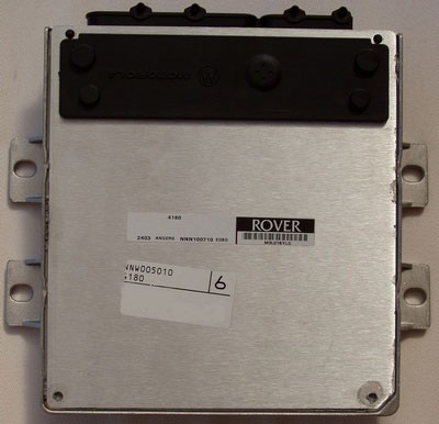
LUCAS MEMS 3 - Pin Outs
Details of the pin usage for the ECU connector(s).

 
1 Upstream oxygen sensor heater – output
2 Down stream oxygen sensor ground – input
3 Downstream oxygen sensor supply – output
4 CKP sensor supply – output
5 CMP sensor ground – output
6 Oil temperature sensor ground – input
7 ECT sensor ground – input
8 MAP sensor supply (5V) – output
9 Differential speed sensor signal (EM-CVT gearbox) - input
10 Oil temperature (VVC only) - output
11 Not used
12 Decrease solenoid valve (VVC) - output
13 IAC valve stepper motor phase B - input/output
14 Injector 3 ground - input
15 Upstream oxygen sensor supply - output
16 CMP sensor signal - input
17 CKP sensor ground - input
18 IAT sensor ground - input
19 Main relay supply signal - input
20 TP sensor signal - input
21 Engine bay temperature sensor signal - input
22 Not used
23 Not used
24 IAC valve stepper motor phase D - input/output
25 Injector 1 ground – input
26 Ignition coil 2 ground – input
27 Downstream oxygen sensor heater (2001 MY onwards) - output
28 Upstream oxygen sensor ground - input
29 Downstream oxygen sensor negative (2001 MY onwards) - input
30 CKP sensor negative – input
31 MAP sensor ground – input
32 Engine oil temperature sensor signal - input
33 ECT sensor signal – input
34 TP sensor ground – input
35 Alternator load signal – input
36 Not used
37 Sensor ground – input
38 EVAP purge valve drive – output
39 IAC valve stepper motor phase A - input/output
40 Injector 4 ground - input
41 Upstream oxygen sensor negative - input
42 CMP sensor ground
43 Not used
44 IAT sensor signal - input
45 MAP sensor signal - input
46 TP sensor supply (5V)
47 Not used
48 Instrument pack - gearbox position display PWM signal - output
49 Increase solenoid valve (VVC) - output
50 IAC valve stepper motor phase C - input/output
51 Injector 2 ground - input
52 Ignition coil 1 ground - input
53 A/C clutch relay coil ground - input
54 Main relay coil ground - input
55 Instrument pack - tachometer drive - output
56 A/C trinary switch hi/low - input
57 Not used
58 Diagnostic K line - input/output
59 Main ground 1 - input
60 Cooling fan relay coil ground - input
61 Ignition switch - input
62 Instrument pack - engine bay overheat warning lamp - output
63 Park/neutral switch - input
64 Rough road sensor positive (non ABS) - input
65 Not used
66 Main ground 3 - input
67 Cooling fan relay 1 coil ground - input
68 Fuel pump relay coil ground - input
69 MIL lamp (2001 MY onwards) - output
70 Trinary switch A/C fan request - input
71 Sensor ground - input
72 Alarm ECU - immobilisation coded signal - input
73 Main ground 2 - input
74 Engine bay cooling fan relay coil ground - input
75 Gearbox interface unit data receive (EM-CTV gearbox) - output
76 Not used
77 Gearbox interface unit data receive (EM-CTV gearbox) - input
78 Road speed signal - input

SM003 - LUCAS MEMS 3 - Diagnostic Capabilities (Read Fault Codes)
Reads the fault code memory. The ECU can self detect up to 47 different problems with itself, its wiring and its associated sensors, storing the respective code if it detects any malfunction or reading outside of predefined acceptable limits. Not all stored faults may cause the fault warning lamp to illuminate.

This function reads the faults from the MEMS fault code memory. This memory not only stores codes associated with GM events which may have occurred in the past and have triggered the code being stored, requiring the memory to be cleared, but also has some internal fault statuses which use the fault memory dynamically, setting a code associated with a missing sensor input, but automatically clearing it whenever the sensor input is being detected again. This means that for some inputs which are only available when the engine is running, such as the crank sensor input, are shown as missing when the engine is stationary. There are over 100 such items.

SM003 - LUCAS MEMS 3 - Diagnostic Capabilities (Clear Fault Codes)
This function diagnostically clears the fault code memory.

SM003 - LUCAS MEMS 3 - Diagnostic Capabilities (Settings)
Values, configuration settings and other stored information which can be read from the ECU, edited and then rewritten back. Read settings can also be stored as a standard HTML page for reference. These pages can then later be re loaded and re written back to the ECU. Please note that some values may be read only due to the fact that they are supplied from the ECU's ROM or are internally calculated.

GENERAL SETTINGS AND INFORMATION
  • GM Number: This is a unique code that identifies the configuration of the vehicle. It is stored in several ECUs within the vehicle and allows the manufacturer to uniquely identify each and every possible option for the vehicle. It is used in conjunction with the SA and VN codes. The number is stored in the instrument pack ECU and in the EWS 3D ECU and can be read in their settings pages.
  • SA Number: This is a unique code that identifies the configuration of the vehicle. It is stored in several ECUs within the vehicle and allows the manufacturer to uniquely identify each and every possible option for the vehicle. It is used in conjunction with the GM and VN codes. The number is stored in the instrument pack ECU and in the EWS 3D ECU and can be read in their settings pages.
  • VN Number: This is a unique code that identifies the configuration of the vehicle. It is stored in several ECUs within the vehicle and allows the manufacturer to uniquely identify each and every possible option for the vehicle. It is used in conjunction with the GM and SA codes. The number is stored in the instrument pack ECU and in the EWS 3D ECU and can be read in their settings pages.
  • VIN Number: Vehicle's identification number.
  • Programming Date: This is the recorded date on which the ECU was programmed.
  • Assembly Number: This is a unique number which defines the ECU hardware and software combination.
  • Hardware Number: This is the hardware version which denotes the processor and circuit board type.
  • Coding Index: The coding index for this ECU.
  • Diagnostic Index: The diagnostic index for this ECU.
  • Application Ident: Non programmable numbers that defines the application identifier for the ECU coding.
  • Calibration Ident: Non programmable number that defines the calibration identifier for the ECU.
  • Boot Ident: Non programmable number that defines the booting identifier for the ECU.
PROGRAMMING RECORDS
  • New Record Entry / Active Record: Areas where new programming data can be entered and current data can be read.
  • VIN Number: Vehicle's identification number.
  • Programming Date: This is the recorded date on which the ECU was programmed.
  • Assembly Number: This is a unique number which defines the ECU hardware and software combination.
  • Homolog. Number: This is the recorded emission control test number (Homologation) which is allocated to the ECU configuration/fuel tune map set by the respective authority.
  • Programming Station: This is a code by which the programming equipment may be recognised. The programming may be done at a number of stages during the life of the ECU by different programming equipment. The most common code is T9999; this denotes Land Rovers own TestBook equipment. X codes usually refer to Bosch programming equipment and are often seen in the 1st record which is created during manufacture.
  • Odometer Value (Km): When re-programming is done which creates a record, it is possible for the programming tool to use this value to record the odometer value of the vehicle to which this ECU was fitted in kilometres. This number could be entered manually, or the equipment could automatically obtain the value by reading the figure electronically from the relevant Body Control Module. Its value is only of some use as the ECU may be moved between vehicles.
  • Unused Data: Data that currently has no known usage but as something is required to be supplied when programming a new record; it has to be filled in. We suggest that you use the same data taken from the last programming record, which can be typed in manually or cut and pasted in using CTRL-C and CTRL-V key combinations.
  • AIF Status: This code, whilst contained in all records, is currently not used for any purpose. It is actually filled with the time of day in hours, minutes and seconds when the re-programming that created this record was performed.
  • Map Database: Shows details relating to ECU programming variations.

SM003 - LUCAS MEMS 3 - Diagnostic Capabilities (Inputs)
Realtime live display of the information the electronic control unit of the selected vehicle system is currently deriving from its input sensors.

ECU READING / SENSOR READING INPUTS
  • ECU Coolant Temperature (°C): Shows the current temperature of the engine coolant. The measurement is taken using the engine coolant temperature sensor. The ECU will automatically calculate a safe default temperature if the sensor reading is implausible. The reading may continue to change even with a faulty or disconnected sensor.
  • Input Coolant Temperature (°C): Shows the actual reading directly from the sensor. No processing or checking is done on this value so the reading will directly indicate any faults present in the sensor or input circuit. By comparing this reading with the ECU processed version it is possible to see when the ECU is using a default value.
  • ECU Engine Oil Temperature (°C): Shows the current temperature of the engine oil. The measurement is taken using the engine oil temperature sensor. The ECU will automatically calculate a safe default temperature if the sensor reading is implausible. The reading may continue to change even with a faulty or disconnected sensor.
  • Input Engine Oil Temperature (°C): Shows the actual reading directly from the sensor. No processing or checking is done on this value so the reading will directly indicate any faults present in the sensor or input circuit. By comparing this reading with the ECU processed version it is possible to see when the ECU is using a default value.
  • ECU Air Temperature (°C): Shows the current temperature of the engine inlet air measured using the inlet temperature sensor. If the sensor reading is out of range, the ECU will automatically calculate a safe default temperature.
  • Input Air Temperature (°C): Shows the actual reading directly from the sensor. The reading will directly indicate any faults present in the sensor or input circuit. By comparing this reading with the ECU processed version it is possible to see when the ECU is using a default value.
  • ECU Manifold Pressure (KPa): Shows the inlet manifold pressure. The measurement is taken using the inlet manifold pressure sensor. The ECU will cross check the reading with throttle position and engine speed and automatically set an estimated value if the sensor reading is implausible.
  • Input Manifold Pressure (KPa): Shows the actual reading directly from the sensor. No processing or checking is done on this value so the reading will directly indicate any faults present in the sensor or input circuit. By comparing this reading with the ECU processed version it is possible to see when the ECU is using a default value.
  • ECU Battery Voltage (V): Shows the vehicle battery voltage. The voltage is measured internally in the MEMS3 ECU using the main relay supply pin.
  • Input Battery Voltage (V): Shows the actual reading directly from the input. No processing or checking is done on this value so the reading will directly indicate any faults present in the sensor or input circuit. By comparing this reading with the ECU processed version it is possible to see when the ECU is using a default value.
  • ECU Upstream Oxygen Sensor Voltage (V): Shows the output voltage of the upstream oxygen sensor. In normal operation this voltage should switch rapidly between two values representing rich or lean fuelling.
  • Input Upstream Oxygen Sensor Voltage (V): Shows the actual reading directly from the sensor. No processing or checking is done on this value so the reading will directly indicate any faults present in the sensor or input circuit. By comparing this reading with the ECU processed version it is possible to see when the ECU is using a default value.
  • ECU Downstream Oxygen Sensor Voltage (V): Shows the output voltage of the downstream oxygen sensor. In normal operation this voltage may switch slowly about an average value. Rapidly depressing the throttle should cause a change in the voltage. Rapid continuous switching of this signal on a fully warm engine indicates a possible catalyst problem.
  • Input Downstream Oxygen Sensor Voltage (V): Shows the actual reading directly from the sensor. No processing or checking is done on this value so the reading will directly indicate any faults present in the sensor or input circuit. By comparing this reading with the ECU processed version it is possible to see when the ECU is using a default value.
FUELLING
  • Throttle Voltage: Shows the voltage measured from the throttle potentiometer. The reading should vary smoothly from near to 0V with the throttle closed to between 4-5V with a fully open throttle. The ECU will provide a default value for this reading if the reading is outside of the expected range or implausible when cross checked against the manifold pressure and engine speed.
  • Engine Speed (RPM): Shows the engine speed in revolutions per minute. The speed is measured using the crankshaft sensor and sensor wheel.
  • Road Speed (km/h): Shows the vehicle road speed in km/h. The speed is measured using the crankshaft sensor and sensor wheel.
  • Road Speed (mph): Shows the vehicle road speed in mph. The speed is measured by the ABS ECU using a wheel speed sensor and is transmitted to the ECU using the CAN bus.
  • Inj 1 PWM (ms): Shows the time the fuel injector is open and injecting fuel into the inlet manifold for cylinder Nš1. Total amount of fuel injected into the engine is also dependent on the number of injectors.
  • Inj 2 PWM (ms): Shows the time the fuel injector is open and injecting fuel into the inlet manifold for cylinder Nš2. Total amount of fuel injected into the engine is also dependent on the number of injectors.
  • Inj 3 PWM (ms): Shows the time the fuel injector is open and injecting fuel into the inlet manifold for cylinder Nš3. Total amount of fuel injected into the engine is also dependent on the number of injectors.
  • Inj 4 PWM (ms): Shows the time the fuel injector is open and injecting fuel into the inlet manifold for cylinder Nš4. Total amount of fuel injected into the engine is also dependent on the number of injectors.
  • Inj Dead Time Adaption (ms): Shows the amount (time) by which the ECU has adapted the injector deadtime. This adaption is a fixed amount of extra injection time which is added on for each injection. The value compensates for errors in the fuelling at idle and has progressively less effect at higher speeds and loads. A high value shown may indicate an air leak problem.
  • Stepper Position (Steps): Shows the calculated position of the idle air control valve. The valve is driven using a stepper motor. When the ignition is switched off the ECU moves the stepper so the valve is in its fully closed position (referred to as referencing) and then opens it by a pre-determined number of steps. The ECU has no method of measuring the position of the valve so it records all the steps applied and works out the position by counting.
  • Fuelling State: Shows the current fuelling strategy that the ECU is operating in. CLOSED LOOP - The ECU is using information from the oxygen sensors to control the fuelling (normal or expected state). OPEN LOOP - The fuelling is being calculated using the standard engine tune only. The feedback state should normally be closed except during cold engine conditions (just after start) or briefly during certain specific driving conditions including rapid or harsh acceleration.
  • Purge Valve %: Shows the value of the purge valve drive. The drive varies between 0% and 100% depending on the amount of vapour purge required. Occasionally the value will exceed this range.
  • Flywheel: Shows whether the ECU has learned the variations in the fitted flywheel sensor. Due to the manufacturing process every flywheel has slight inaccuracies in the positions of the marker teeth on the wheel. This in turn makes misfire detection unreliable until the ECU has learned to compensate for these small errors. Adaption occurs during normal driving. If the flywheel adaption is 'NOT ADAPTED' then misfire detection will be disabled.
  • Cat Condition: Shows the status of the catalyst. NORMAL - The catalyst is working normally. DEGRADED - The MEMS3 on board diagnostics have detected that the catalyst performance has become degraded. Only valid on vehicles with both upstream and downstream oxygen sensors fitted.
  • Sensor State: Shows the oxygen sensor status. NORMAL - The oxygen sensors are working normally. DEGRADED - The MEMS3 on board diagnostics have detected that the oxygen sensor performance has become degraded.
  • Fuel Correction %: Shows the current fuelling correction applied to the amount of fuel injected. The correction is calculated using information derived from the oxygen sensors. No correction being applied is represented by a reading of 100%. A high reading indicates that the fuel is being corrected for a mixture which was too lean, a low reading for a mixture that was too rich.
  • Misfire Cyl 1/2/3/4: Shows the number of misfires which have occurred on the respective cylinder number since the start of the current misfire sample period. This includes faults such as fuel and compression leak problems. Inaccuracies in the misfire detection system are possible so some false detections will happen. MISFIRE: - Any combustion event that occurs but does not produce the expected power output.
  • Cat Test Result: Shows the results of the on board diagnostic catalyst test. The value should be read in conjunction with the CAT LIMIT. Valid only on vehicles with both upstream and downstream oxygen sensors fitted.
  • Cat Limit: Shows the catalyst test limit. Display shows the maximum permitted limit for the results of the on board diagnostic catalyst test. The value should be read together with the CAT TEST. Valid only on vehicles with both upstream and downstream oxygen sensors fitted.
  • Cat Test: Shows the current state of the ECU Catalyst test. COMPLETE - The ECU has successfully completed the test. INCOMPLETE - The testing process is still ongoing or the conditions for the test are not correct. Only to be carried out on vehicles equipped with upstream and downstream oxygen sensors.
GENERAL PAGE 3
  • Coil 1 Charge Time (µs): Shows the time taken for the current in coil 1 to build up to its maximum value. It is not normally expected that the coils will reach this value of current except at low engine RPM. If the maximum current is reached the time should be between 1500 - 3000 µS (1.5 - 3mS) with a fully charged battery.
  • Coil 2 Charge Time (µs): Shows the time taken for the current in coil 2 to build up to its maximum value. It is not normally expected that the coils will reach this value of current except at low engine RPM. If the maximum current is reached the time should be between 1500 - 3000 µS (1.5 - 3mS) with a fully charged battery.
  • Idle Error Speed (RPM): Shows the deviation of the engine speed from the target engine RPM for idle speed control. A higher than desired value is indicated by a positive reading and a lower than desired by a negative reading. The value is only meaningful while the engine is in closed loop idle speed control.
  • Ignition Offset (°): Shows the value of any ignition service offset which has been programmed into the ECU. Adjustments can be made via the Other options.
  • Idle Speed Adjustment (RPM): Shows the value of the idle speed adjustment. This adjustment is not supported on all vehicle types.
  • Engine Roughness: Shows the amount of unevenness in the engine. A high value may be an indication of a problem with the engine fuelling, ignition or there could be a mechanical problem with the engine such as poor compression or incorrect cam timing.
  • Rough Threshold: Shows the current threshold value for the engine roughness. The threshold value is dependent on the engine operating conditions. Misfires are counted when the engine roughness value exceeds this threshold.
  • CAT %: Shows the current percentage for the counter recording misfires in the catalyst damaging misfire sample period. A catalyst damaging misfire fault would normally be written when the value reaches 100%.
  • Emission %: Shows the current percentage for the counter recording misfires in the emission relevant misfire sample period. An emission relevant misfire fault would normally write when the value reaches 100%.
  • Rough Road %: Shows the percentage of rough road events.
  • Rough Road 1 %: Shows the percentage of rough road events (potential misfires) measured in engine operating range 1.
  • Rough Road 2 %: Shows the percentage of rough road events (potential misfires) measured in engine operating range 2.
  • Engine Torque %: Shows the current engine torque available expressed as a percentage of the maximum torque. Value for informational use only.
  • Engine Torque (Nm): Shows the current calculated value of engine torque. This value is calculated by the ECU using mainly the engine speed and manifold pressure.
  • Gearbox Torque %: Shows the current engine torque value which is being sent to the automatic gearbox ECU. Value for informational use only.
  • Current Gear: Shows the current gear which the automatic gearbox has selected. In some cases this may not always be the same gear specified by the gear selector lever.
  • Selector Position: Shows on automatic vehicles the current gear selector position. There may be a problem with the CAN BUS between the MEMS3 and the Automatic Transmission ECU if the value does not correspond to the actual selector position. Check for stored fault codes on the Automatic Transmission ECU and MEMS3.
  • Idle Set Point: Shows the target engine RPM for idle speed control. This value will initially be high at low coolant temperature and progressively reduce as the engine warms up. Additional loads applied such as air conditioning may cause a small increase to be noticed.
  • Idle Dead Band Position (Steps): Shows the learned IACV (idle air control valve) stepper position for idle on a fully warm engine. This value will adapt for engine and idle component wear. The adaption allows for a quicker return to the correct idle point when idle is entered. This adaption helps to prevent engine flare or stalling.
  • Idle Power Steering Pressure: Shows the current pressure of the power assisted steering fluid. The ECU uses this pressure to measure the expected engine loading caused by power steering. The ECU will increase the stepper position at higher values of PAS pressure to prevent the increased load lowering the idle speed. The PAS pressure should rise as the steering wheel is moved with the engine at idle. Failure of this system may lead to reduced idle quality when power steering is in use.
  • Idle Close Throttle (V): Shows the learned closed throttle voltage. The ECU uses this voltage for determining whether the throttle is closed or partly open. The voltage will adapt downwards if the throttle voltage is measured as lower than the closed throttle volts. Upwards adaption only occurs if the throttle voltage is slightly higher than the closed throttle voltage. If the throttle voltage is any higher than this value when the throttle is closed then adjustment is necessary.
  • Idle Alternator Load %: Shows the current alternator load percentage. The ECU uses this value to measure the expected engine loading caused by electrical loads on the vehicle. It will then increase the stepper position at higher values of alternator load to prevent the increased load lowering the idle speed. The alternator load should rise as electrical loads (such as rear screen heater) are switched on with the engine at idle. Failure of this system may lead to reduced idle quality as loads are switched on and off. This reading is dependant on the condition of the vehicle battery.
  • Ambient Air Temperature (°C): Shows the current ambient air temperature. The ECU uses this value to provide minor adjustments to the IACV (idle air control valve) stepper position and to fuelling. Failure of this sensor may lead to slightly reduced idle quality and slightly impaired starting.
  • A/C Evaporator Temperature (°C): Shows the current air conditioning evaporator temperature. This value is used to control air conditioning. Failure of this sensor can result in the air condition not working.
  • A/C Torque Demand %: Shows the current engine torque calculated to be required by the air conditioning. This value is used for idle speed control to allow better adaption of the IACV (idle air control valve) stepper position and to improve idle quality.
  • Idle Control Aborted: Shows whether closed loop idle control has been aborted due to the vehicle conditions. Conditions being could include vehicle not stationary, idle error RPM too high or throttle not closed.
  • Throttle Status: Shows whether the ECU considers that the throttle is fully closed or not. It will see the throttle as closed if the throttle voltage is within a few mV's (millivolts) of the closed throttle voltage. It is possible for the idle speed control to fail and in turn may cause overrun problems and stalling if the closed throttle position is not correctly determined.
  • Stepper Movement: Shows whether the ECU is currently permitting the stepper to move. Stepper movement is inhibited under certain conditions e.g. when the battery volts are low.
  • Fast Idle: Normally this value will only be active immediately after closing the throttle. This value is normally only active immediately after closing the throttle. Its is the period immediately after going into the idle speed control where the ECU is trying to bring the engine speed down form a high value to the target idle speed.
  • Idle Condition: Shows the results of the ECU checking for closed throttle and engine speed conditions before idle is allowed. The idle can be inhibited by certain conditions which can include problems with throttle adjustment, closed throttle settings and or air leaks.
  • Idle Control Requested: Shows when the ECU is attempting to start and run the idle speed control system. Normally this request would result in closed loop idle speed control. Problems with stabilising the engine speed may prevent this.
  • Drive/Neutral Status: Shows whether the ECU is currently reading the gearbox selection as drive or as neutral. This information is used to determine if the conditions are correct for idle speed control and to add extra steps to the IACV stepper motor to compensate for extra frictional losses in the automatic transmission when drive is selected. Failure of this system will lead to sudden changes in engine RPM during transitions between drive and neutral.
  • Fuelling Idle Adjustment: Shows the value of the fuelling service adjustment. This adjustment is currently not supported all vehicle types.
  • Vehicle Stationary: Shows whether the ECU has decided if the vehicle is currently moving or stationary. If the movement status incorrectly determines that the vehicle is moving then idle speed control will not be entered. If the movement status incorrectly determines that the vehicle is stationary then idle speed control may interfere with driving the vehicle.
  • Ignition Torque Retard (°): Shows the value of any ignition retard being currently applied by the ECU on the request from the gearbox. Improved shift quality is achieved with the retard as it is used to reduce engine torque during gear changes.
GENERAL PAGE 4
  • Cam Sync: Shows whether the ECU has synchronised the engine position with the camshaft sensor. If this flag is set the engine fuelling and misfire detection may be mistimed. This problem may cause an increase in emission from the vehicle.
  • Crank Sync: Shows whether the ECU has managed to read the crankshaft signal input and synchronise to the current engine rotational position. Crank sync must be CORRECT before the engine will run. If NO SYNC is displayed when the engine is cranked there may be a problem with the crankshaft sensor or the sensor wheel.
  • Sync Lost: Shows whether the ECU has lost sync at some point since the engine started. If this occurs frequently it may indicate poor performance of the crankshaft sensor and sensor wheel. High speed intermittent misfire or hesitation/stalling are possible symptoms of this problem. Intermittent loss of 12V power to the MEMS ECU can also generate this.
  • Crank Pos %: Shows the current calculated position of the crankshaft. Calculation is achieved by counting the crankshaft sensor pulses and interpolation. It is only valid when crank sync is correct. This reading will move too rapidly to be read normally, except during cranking.
  • Sync Status: Only valid after an attempt to re-synchronise the security code between the Immobiliser ECU and the MEMS3 ECU. The reading will show RESYNCHRONISED if synchronisation was required and works correctly otherwise NOT REQUIRED is displayed. NOT REQUIRED is also shown if the Immobiliser ECU and the MEMS3 ECU do not match.
  • New System: Shows if the MEMS3 ECU is a new system or if it has previously learned a security code. Once this is set by a code learn operation then only re-synchronisation is allowed there after. This being set prevents MEMS3 ECUs being successfully swapped between vehicles.
  • Sync Allow Conditions: Shows if conditions are correct for re-synchronisation. The reading will show INVALID CONDITIONS if conditions do not permit re-synchronisation an example for this being if the engine is running.
  • Learn Status: Only valid after a security code re-sync or learn operation have been carried out. It shows if the operation was successful or failed. If the MEMS3 ECU had previously learned a different code it will fail.
  • Immobiliser Comms: Shows the current state of the ECU Immobiliser input signal. This is set to SIGNAL OK if the MEMS3 detects ANY activity on its security input. A single pulse is enough to set this to SIGNAL OK. The signal may still be invalid even though it is present. Once set to OK it will not be reset until the ignition is switched off.
  • Immobiliser State: Shows the current state of MEMS3 immobilisation. If the value shows OK the ECU has received at least one correct security code since the ignition was switched on otherwise there has been no signal transmitted between the Immobiliser ECU and MEMS3 or the signal did not contain the correct code. If the value shows IMMOBILISED the engine will start and fire once for about 1 second and then stop as the fuel injections are inhibited. If the ignition is switched off for approx. 20 seconds this sequence will repeat.
  • Code Learned: Only valid after a security code learn operation on a NEW MEMS3 ECU. Shows if the code learn operation stored a correct or corrupted security seed. Shows if the operation was successful or failed. An example of fail being if the MEMS3 ECU had previously learned a different code.
  • Program: Only valid after a security code learn operation on a previously used MEMS3 ECU. Shows that the code learn operation was rejected (not allowed because the ECU was not new). An example of fail being if the MEMS3 ECU had previously learned a different code.
  • Resync: Only valid after a security code re-synchronisation operation on a MEMS3 ECU which does not match the Immobiliser ECU. Shows that the code re-sync operation was rejected - not allowed because the ECU had previously learned a seed from a different Immobiliser ECU.
  • Seed Stat: Shows the state of the stored security seed. If the seed is corrupt, try to re-learn the security code.
  • Immobiliser Comms Stat: Shows if any errors have been detected in the communications link between the Immobiliser ECU and the MEMS3 ECU. The security learn operation is not allowed if this is set. To clear/reset this, turn the ignition off for 20 seconds and then restore it to position 2.
  • Code Type: Shows if the MEMS3 ECU is receiving the expected security code or an incorrect code. An incorrect code may indicate an attempt to fit a previously used MEMS3 ECU to the vehicle.
  • Immobiliser Rolling Code: Shows the current count of the rolling security code between the MEMS3 ECU and the Immobiliser ECU. This count is reset to 1 when the security code is re-synchronised.
  • Good Immobiliser: Shows the current count of good security mobilisation attempts where the security code between the MEMS3 ECU and the Immobiliser ECU was correctly recognised. In normal operation at least one good Immobiliser ECU event should be counted for each ignition on.
  • Bad Immobiliser: Shows the current count of bad security mobilisation attempts where the security code between the MEMS3 ECU and the Immobiliser ECU was not correctly recognised. In normal operation occasional bad Immobiliser ECU counts are acceptable - typically one per start.
  • Security Link: Shows whether the security link input to the MEMS3 ECU is currently high (>5v) or low (<5v). If the correct key is inserted in the ignition this signal should constantly vary between low and high. If the signal does not change check the security communications link between the MEMS ECU and the Immobiliser ECU. If the signal is changing then a signal is being received by the MEMS3 ECU.
  • Ignition Switch: Shows whether the MEMS3 ECU is reading the state of the ignition switch input as either ON or OFF.
  • Slow Fans Request: Shows whether the ECU is seeing a request from the air conditioning system for fan on. The actual fan behaviour will depend on a combination of this request and the coolant temperature. If this request is combined with raised coolant temperature then both fan drives will be activated leading to high speed fan operation.
  • A/C Request: Shows if the ECU is a receiving a request to activate air conditioning. Under normal engine running conditions the air conditioning clutch will be activated a few seconds after the request signal.
  • A/C Switch: Shows whether the Aircon request switch is on or off. On some vehicles this switch is automatically controlled by the passenger compartment temperature controls. When the switch is on, the MEMS3 ECU will activate the air conditioning compressor so long as no faults are present. Failure of this system will cause the air conditioning to be permanently on or off.
  • Gearbox Status: Shows whether the ECU is currently reading the gearbox selection as drive or neutral. This information is used to determine if the conditions are correct for idle speed control and to add extra steps to the IACV (idle air control valve) stepper motor to compensate for extra frictional losses in the automatic transmission when drive is selected. Failure of this system will lead to sudden changes in engine RPM during transitions between drive and neutral.
  • Throttle Status: Shows whether the ECU is currently reading the throttle position as open or closed. This status is calculated using the throttle potentiometer voltage and is important in determining the engine operation during idle. If the status reads OPEN when the throttle is not being pressed then a fault or incorrect adjustment is present.
  • Idle Speed Control Status: Shows whether ECU is currently controlling the idle engine RPM. CLOSED LOOP - The ECU is using the engine speed and other information to move the IACV (idle air control valve) stepper motor to a position which gives the required idle RPM. OPEN LOOP - Idle speed control is not operating. If the status shows OPEN LOOP during idling conditions then a problem is present.
  • Crank Status: Shows whether the ECU is currently running with cranking ignition and fuelling. Cranking will be active between the STOPPED and STARTING stages of the engine crank to run process. If CRANKING is not seen when the engine is cranking, check the crankshaft sensor input and crank position real time display.
  • MEMS Running Status: Shows whether the ECU is currently running with STARTING or RUNNING ignition and fuelling. Starting will be active after the CRANKING stage of the engine crank to run process is complete. If STARTING is not seen when the engine has been cranking for a few moments then this may indicate a problem with the crankshaft sensor or wheel. Check that CRANK SYNC is correct after 1 - 2 engine revs and SYNC LOST does not log any faults.
  • MEMS Stop Status: Shows whether the ECU is currently in STOPPED mode. STOPPED mode indicates that the ECU is not seeing any engine rotation and is inhibiting all ignition and fuel. If STOPPED remains active when the engine is cranked there may be a problem with the crankshaft sensor.
GENERAL PAGE 5
  • CAN TX Faults: Shows the number of CAN message transmit faults recorded by the MEMS3 ECU. These faults can be caused by problems with either the CAN bus, the MEMS3 ECU, the automatic transmission ECU or the instrument pack ECU.
  • CAN RX Faults: Shows the number of CAN message receive faults recorded by the MEMS3 ECU. These faults can be caused by problems with either the CAN bus, the MEMS3 ECU, the automatic transmission ECU or the instrument pack ECU.
  • Autobox Message: Shows if the MEMS3 ECU has received an expected message from the automatic gearbox ECU over the CAN communication bus. The status will be WAITING if the vehicle does NOT have automatic transmission. If the vehicle has automatic transmission and the status is always WAITING then a fault is present.
  • Instr 2/3/4 Message: Shows if the MEMS3 ECU has received an expected message from the instrument pack ECU over the CAN communication bus. A fault is present if the status is always WAITING.
  • CAN Autobox Message: Shows if the CAN communication link between the MEMS3 ECU and the automatic transmission ECU has timed out. NOTE: This may be always set if the vehicle does not have automatic transmission. If the vehicle has automatic transmission and the status is MESSAGE TIMEOUT then a fault is present.
  • CAN ID2/3/4 Message: Shows if the CAN communication link between MEMS3 and the instrument pack ECU has timed out. OK - CAN communications are normal. MESSAGE TIMEOUT - a fault is present.
  • CAN System: Shows the state of the CAN communication system internal to the MEMS3 ECU. If the status is always INTERNAL FAULT and other ECUs connected to the MEMS3 indicate no CAN communication, a possible MEMS3 internal fault may exist.
  • CAN Node: Shows the state of the CAN communication system internal to the MEMS3 ECU. If the status is always FAULT - NO NODES and other ECUs connected to the MEMS3 indicate no CAN communication, a possible MEMS3 internal fault may exist in this case.
  • CAN RAM: Shows the state of the CAN communication system internal to the MEMS3 ECU. If the status is always FAULT - NO NODES and other ECUs connected to the MEMS3 indicate no CAN communication, a possible MEMS3 internal fault may exist in this case.
  • CAN TX State: Shows the state of the CAN transmission system. TX FAULT - this indicates that the MEMS3 cannot send CAN messages to another ECU.
  • CAN RX State: Shows the state of the CAN reception system. RX FAULT - this indicates that the MEMS3 cannot receive CAN messages from another ECU.
  • CAN BUS State: Shows the state of the CAN communication system. BUS FAULT - this indicates that the MEMS3 has detected a problem with the can BUS system.
GENERAL PAGE 6
  • Upstream O2 Switching Frequency (Hz): Shows the time taken for the upstream oxygen sensor to switch between rich to lean or lean to rich. The switching time depends on the engine operating conditions and the sensor temperature. A reading of 100% shows that no correction is being applied. A High reading shows that the fuel is being corrected for a mixture which was too lean, a low reading for a mixture that was too rich.
  • Upstream O2 Sensor Switch (S): Shows the time taken for the oxygen sensor to switch.
  • Fuelling Feedback Status: Shows if MEMS3 ECU is operating with OPEN LOOP or CLOSED LOOP fuelling. If the ECU operates with OPEN LOOP fuelling continuously or always switches to open loop after a few seconds and then stays OPEN LOOP, then a fuelling fault is present.
  • Fuelling Feedback Switch: Shows whether the ECU is currently reading the presence of oxygen in the exhaust gases. When oxygen is present (as indicated by the oxygen sensor) the status will show FUEL LEAN otherwise it will show FUEL RICH. The display RICH/LEAN indicates whether the ECU is determining the presence of a rich or lean mixture. Caution is required in interpreting this result however, if an ignition misfire or air leak into the exhaust is present the ECU will only see the excess oxygen and may incorrectly display FUEL LEAN when in fact there is unburned fuel in the exhaust gas. In normal operation this display should continuously switch rapidly between FUEL LEAN and FUEL RICH.
  • Upstream O2 Status: Shows whether the upstream (pre catalyst) oxygen sensor is warmed up and ready for use in fuelling feedback. A fault may be present if the value shows the sensor is not ready for more than a few minutes.
  • Upstream Duty Ratio %: Shows the current amount of heating being applied to the upstream (pre catalyst) oxygen sensor.
  • Upstream O2 Heat (A): Shows the upstream oxygen sensor heater current. This value will initially be high when the oxygen sensors are cold but should rapidly reduce to a low value.
  • Oxygen Heater Drive: Shows the upstream oxygen sensor heater current. This value will initially be high when the oxygen sensors are cold but should rapidly reduce to a low value.
  • Main Relay: Shows whether the MEMS3 ECU is currently driving the main relay ON or OFF. The main relay should normally be ON whenever the ignition switch is ON.
  • Fuel Pump: Shows whether the ECU is currently driving the fuel pump relay ON or OFF. Normally the fuel pump is driven ON for a few seconds after the ignition is switched on and then is turned OFF until an engine speed signal is detected.
  • A/C Drive Status: Shows whether the ECU is currently driving the Aircon clutch to engage the compressor. The compressor will normally be driven on if air conditioning is requested and certain conditions are met. The required conditions are shown below: Air temperature below set point - refrigerant pressure above minimum permitted - refrigerant pressure below maximum permitted - coolant temperature below maximum permitted (measured with engine coolant temperature sensor) - Engine is running.
  • RAD Fan Drive: Shows whether the MEMS3 ECU is driving the relay for fan 1 on or off. If either fan 1 or fan 2 relay is driven on the radiator fan will run at slow speed. The radiator fan runs at high speed if both fan relays are switched on.
  • AUX Fan Drive: Shows whether the MEMS3 ECU is driving the relay for fan 2 on or off. If either fan 1 or fan 2 relay is driven on the radiator fan will run at slow speed. If both fan relays are switched on the radiator fan runs at high speed. Normally the Fan 2 relay is not driven on without fan 1 relay also being driven on.
GENERAL PAGE 7 (This display is not valid if no 'MIL ON' event has occurred.)
  • FAULT CAUSING MIL: The fault status display shows the information about the fault which is causing the MIL light to be on.
  • FREEZE FRAME TRIGGER FAULT: This freeze frame is stored by the most recent confirmed fault which has set the MIL on request.

SM003 - LUCAS MEMS 3 - Diagnostic Capabilities (Outputs)
Choice of outputs that can be tested. Each output apart from the cooling fan has an ON and OFF choice. Click on the ON link to start the test and on OFF to end.

  • Main Relay: On / Off switching options for the main relay.
  • Fuel Pump Relay: On / Off switching options for the fuel pump relay.
  • A/C Clutch Relay: On / Off switching options for the A/C clutch relay.
  • Fan PWN Control: Options to drive the fan to 10% or 90% of its full operational output.
  • Return Outputs Under ECU Control: Re-establishes ECU control of the outputs.

SM003 - LUCAS MEMS 3 - Diagnostic Capabilities (Other)
Choice of functions that can be performed:

  • Start Synchronization with immobiliser ECU: This causes the engine management ECU to go into Learn Mode where it will learn the next output from the immobiliser ECU and synchronize with it.
    The synchronization procedure is done in three steps that should take place in one ignition cycling.
    1. Put the engine management in learning mode: This function is to be found in the engine management START SYNCHRONIZATION WITH IMMOBILISER ECU. The function will set the ECU into learning mode. Once you've been prompted that the engine management is in learning mode, navigate in the Vehicle Explorer to the immobiliser for step 2.
    2. Send code from immobiliser ECU: This function is to be found in the immobiliser SYNCRONIZE WITH ENGINE MANAGEMENT SYSTEM. This function will send codes to be learned. Once you've been prompted that the immobiliser sent the code successfully, navigate in the Vehicle Explorer to the engine management for step 3.
    3. Take the engine management out of learning mode: This function is to be found in the engine management END SYNCHRONIZATION WITH IMMOBILISER ECU. The function will end the learning mode, leaving the ECU in normal mode.
  • Read ECU Status: This reads the security line status and the ECU status (NEW/USED). The reading will show if MEMS3 ECU receives any signal from immobiliser ECU and if the codes are valid. It can also determine if the ECU is new, if it already learned a code from immobiliser ECU or it is mobilised.
  • Read/Reset Throttle Position Status: This requires the engine not to be running and ignition on.
  • Reset Fuelling Adaption: This causes the MEMS 3 ECU to reset the adaptive values for the fuelling and relearn them. Reset fuelling adaption to 100% should only be needed if one of the following components have been replaced or rectified:
    • Fuel injector or oxygen sensor
    • Fuel pump or fuel rail
    • Inlet manifold pressure sensor
    • Inlet manifold or air leak repair
    On a vehicle with no faults carrying out this procedure may actually worsen the engine emissions.
  • Reset Flywheel Adaption: This causes the MEMS 3 ECU to reset the adaptive values for the flywheel and relearn them. This is only needed if one of the components have been renewed:
    • Engine
    • Flywheel
  • Reset Idle Adaption: This causes the MEMS 3 ECU to reset the adaptive values for the idle and relearn them. ECU idle adaptions will now be set to the current idle position. Please ensure that the vehicle is fully warmed and idling correctly. If the vehicle in not currently idling correctly this procedure will make the fault worse. ECU idle adaptions should be ONLY be reset if any of the following faults have been corrected.
    • Air leak.
    • Throttle adjustment.
    • Coolant or oil temperature sensors.
    • Any fault affecting engine efficiency.
    This adaption can only be reset when the engine is fully warmed and closed loop idle control is operating. Please note that even if the adaption is not reset it will automatically adjust to the current settings, however this may take several driving cycles to fully complete.
  • Reset All Adaptions: This causes the MEMS 3 ECU to reset all adaptive values and relearn them. CAUTION: The values set up by this procedure are only suitable for engines which are new. The procedure will prevent verification of any repairs carried out until the vehicle has re-adapted. All fault information will be erased. Idle performance and general driveability may be impaired until readaption has occurred.
  • Service Ignition Offset: MEMS3 is programmed with a maximum and minimum permitted offset. If the button pressed exceeds this value then the displayed offset will not change. Some ECUs may be programmed not to accept any other value than 0. CAUTION: Changing the ignition offset to a value which is not appropriate may damage the engine.
  • RETARD: Retarding the ignition offset may be required if the vehicle is being run on fuel with a lower octane rating than the value specified for the vehicle. The retarded ignition will help to reduce detonation, also known as knocking or pinking. This will also have the effect of slightly reducing vehicle power and possible causing the engine to require more cooling due to reduced engine efficiency.
  • ADVANCE: Advancing the ignition should not be necessary. This procedure is only applicable to special vehicles. CAUTION: Applying ignition advance offset may damage the engine.