The Automatic Temperature Control (ATC), manufactured by Nippon Denso, has no external diagnostic serial communication capabilities. Instead, the ATC has all of its diagnostic facilities built into it and access is gained to these merely by pressing the right buttons at the right time. The LCD display is then used to display its findings. The test sequence is initiated, by simultaneously holding down both the AUTO and Mode buttons and whilst still holding these turning on the ignition to stage II. The display will then flash all of display icons 4 times at one second intervals, to show that they are working. It will then, having performed a self test cycle, show the letters FC on the left hand end of the display, with the right hand end flashing the sequence of fault code numbers, in the order that they were logged in memory. The list will always end in 00 to show that this is the end of the list, and if all that is shown is the flashing 00 this means that no faults are stored. It is also very common to see both faults 21 and 22, which are to do with the solar sensors; this will usually be due to the light level being too low for them to register when the test is made. If a fault is detected during usage of the system, it will flash its display and make an audible warning to the driver for several seconds. When a fault code is read from the display choose the button with that codes number on it from the buttons on the menu to give a brief description of the are of the ATC system that the fault covers but use the help for that button to see a vast amount of information about the meaning of the fault, including the symptoms, the exact logical requirements for the fault to be logged, possible causes, expected values and resistances, what the sensor is used for, what default value is substituted, any sensor locations and removal requirements, test information, handy quick check help.
- FAULT CODE 11
In-Car Temperature Sensor - mounted behind a small grill in the fascia, between the steering wheel and driver’s door. To gain access, drop the cover below the steering wheel and remove the grill. The sensor is used to measure the temperature inside the passenger compartment. Because the sensor is located on the driver's side, the temperature on the passenger side is estimated. The sensor incorporates a small fan, which draws air from the passenger compartment over the sensor. This ensures that the sensor measures the passenger compartment air, not the air behind the fascia where the sensor is located.
Symptoms: Set temperatures are not obeyed - Note that, due to radiation compensation and to the complexities of differential temperature control within a small space, it is not valid to expect the In Car Temperature Sensor to correspond to the Set temperature on the display. The default temperature for this sensor is 25º C. This sensor is a thermistor. The resistance of a thermistor varies with temperature. It is the lower resistor of a voltage divider pair and is connected directly to the upper resistor via the ATC ECU input. The other side of the thermistor is connected to signal Gnd. The upper resistor is contained in the ATC ECU and is pulled up to the 5 Volt sensor supply. Upper Resistor value = 1400 Ohm
Fault code 11 is flagged if the in car temperature sensor reads less then -50º C (open circuit) or more then 155º C (short to ground).
The ATC ECU diagnostics will not detect stuck readings due to partial wiring shorts. Therefore, check that the sensor resistance is actually changing with temperature. As the temperature of the thermistor varies, the resistance should vary in the following manner: 0(c = 5636 Ohms, 5(c = 4359 Ohms, 10(c = 3402 Ohms, 15(c = 2678 Ohms, 20(c = 2125 Ohms, 25(c = 1700 Ohms, 30(c = 1370 Ohms)
Remember that no voltage should be present when making measurements with a resistance meter.
- FAULT CODE 12
Ambient Air Temperature Sensor - mounted behind the front grill on the LHS immediately in front of the radiator. Remove the front grill to gain access. The temperature displayed when the ATC ECU EXT button is pushed will not always be the current reading from this sensor. If the vehicle speed falls below 15 Km/h the reading is frozen and will not be updated again until the vehicle exceeds 25Km/h or a time period of two hours expires or the value drops below its 15Km/h value. The air outlet behaviour during warm up will depend on the ambient temperature. The condenser will not be switched on if the ambient temperature is below 28º C. An ambient air temperature below -20º C is required to enable the Heated Front Screen Wind Chill Mode.
Symptoms: Condenser Fan operation is incorrect, Front Screen Wind Chill Mode does not operate, poor cold start warm up control, External Air Temperature display is incorrect.
The default temperature for this sensor is 10º C. However, when default occurs the condenser fan will not be disabled and the external temperature display will show --. This sensor is a thermistor. The resistance of a thermistor varies with temperature. It is the lower resistor of a voltage divider pair and it's connected directly to the upper resistor via the ATC ECU's input. The other side of the thermistor is connected to signal Gnd. The upper resistor is contained in the ATC ECU and is pulled up to the 5 Volt sensor supply. Upper Resistor value is 1400 Ohm
Fault code 12 is flagged if this sensor reads less then -53º C (open circuit) or more then 155º C (short to ground).
The ATC ECU diagnostics will not detect stuck readings due to partial wiring shorts to ground; therefore, check that the sensor resistance is actually changing with temperature. As the temperature of the thermistor varies, the resistance should vary in the following manner: 0(c = 5636 Ohms, 5(c = 4359 Ohms, 10(c = 3402 Ohms, 15(c = 2678 Ohms, 20(c = 2125 Ohms, 25(c = 1700 Ohms, 30(c = 1370 Ohms
Remember that no voltage should be present when making measurements with a resistance meter.
- FAULT CODE 13
Evaporator Temperature Sensor - located within the evaporator body. The Air Con Unit must be removed from the vehicle and opened, to access this sensor. However the sensor wire exits the Air Con Unit on the LHS and (on RHD vehicles only) the connector at this point is accessible without removing the Air Con Unit. This connector is wrapped in foam to prevent rattle and this must be replaced. This sensor monitors the air temperature at the output of the Air Conditioning Evaporator. The purpose of this sensor is to prevent ice from forming in the evaporator fins. If the measured evaporator temperature drops below 3º C the ATC will disable the Air Conditioning Pump and the Condenser Fan. The evaporator must then rise above 4º C before the pump and fan are enabled.
Symptoms: Air Con does not come on, evaporator fins are blocked with ice and Air Con operates at reduced efficiency.
Default temperature for this sensor is 0º C
This sensor is a thermistor. The resistance of a thermistor varies with temperature.
It is the lower resistor of a voltage divider pair and is connected directly to the upper resistor via the ATC ECU input. The other side of the thermistor is connected to signal Gnd. The upper resistor is contained in the ATC ECU and is pulled up to the 5 Volt sensor supply. Upper resistor value is 2370 Ohm.
Fault code 13 is flagged if this sensor reads less then -57º C (open circuit) or more then 135º C (short to ground).
The ATC ECU diagnostics will not detect stuck readings due to partial wiring shorts; therefore, check that the sensor resistance is actually changing with temperature. As the temperature of the thermistor varies, the voltage at the input and the resistance should vary in the following manner : 0(c = 3.37 Volts = 4851 Ohms, 5(c = 3.08 Volts = 3758 Ohms, 10(c = .78 Volts = 2951 Ohms, 15(c = .49 Volts = 2333 Ohms, 20(c = .22 Volts = 1872 Ohms, 25(c = .94 Volts = 1494 Ohms, 30(c = .71 Volts = 1220 Ohms.
Remember that no voltage should be present when making measurements with a resistance meter.
- FAULT CODE 14
Water Temperature Sensor - located at the bottom LHS of the Air Conditioning Unit, obscured by trim. It is clipped to the side of the Water Heater Matrix and can be slid out once the clip retainer has been freed. This sensor monitors the water temperature at the inlet of the water heater matrix. Note that the temperature being measured is the matrix casing temperature, which will normally be about 10º C lower than the actual water temperature. Water temperature is used by the Blower Controller, Air Blend Controller and Air Output Controller to achieve the set temperature. Blower volume is proportionally restricted when water temperature is below 50º C to prevent occupant discomfort. Air outlet behaviour during warm up will depend on the water temperature.
Symptoms: Poor temperature control, poor cold start warm up control, cold air is blasted out during warm up, timed feet does not work.
Default temperature for this sensor is 70º C. This sensor is a thermistor. The resistance of a thermistor varies with temperature. It is the lower resistor of a voltage divider pair and is connected directly to the upper resistor via the ATC ECU input. The other side of the thermistor is connected to signal Gnd. The upper resistor is contained in the ATC ECU and is pulled up to the 5 Volt sensor supply.
Fault code 14 is flagged if this sensor reads less then -40º C (open circuit) or more then 160º C (short to ground). The ATC ECU diagnostics will not detect stuck readings due to partial wiring shorts. Therefore check that the sensor resistance is actually changing with temperature. As the temperature of the thermistor varies, the resistance should vary in the following manner: 0(c = 17092 Ohms, 5(c = 13132 Ohms, 10(c = 10184 Ohms, 15(c = 7969 Ohms, 20(c = 6287 Ohms, 25(c = 5000 Ohms, 30(c = 4006 Ohms
Remember that no voltage should be present when making measurements with a resistance meter.
- FAULT CODES 21 & 22
Right/Left Hand Side Solar Radiation Sensor - The left hand side and right hand side solar radiation sensors are incorporated into a single package, which is mounted in the centre of the dashboard shelf. When removing the connector, take care not to lose it through the mounting hole as it is difficult to retrieve. These sensors are used to compensate for LHS or RHS solar loading. The system will decrease the degree of warming applied to the side of the vehicle receiving the sunlight.
Symptoms: Temperature feels too warm in sunshine.
Fault codes 21 and 22 are associated with the LHS and RHS Solar Sensors. These faults will be flagged if there is an electrical fault on the sensor input line or a fault with the sensor itself. These faults will also be flagged under low light conditions such as an overcast winters day, artificial lighting or at night. Therefore these fault codes will often be displayed and can usually be ignored. These sensors require a 5 Volt supply. The sensors consist of photo conducting diodes. The diodes conduct between 0 - 175 micro Amps depending on the incident light. The current can be measured indirectly by back-probing the sensor line and measuring the voltage in mV. In darkness the voltage should be zero.
- FAULT CODES 31 & 32
Right/Left Hand Side Air Blend Servomotor Control - located on either side of the Air Con Unit at the rear. The Air Con Unit should be removed from the vehicle to gain access to the motors. The Air Blend Servomotors are used to drive a mixer valve mechanism, which blends hot and cold air to produce the correct blower air temperature. A potentiometer is used to feed back the position of the mechanism.
Symptoms: Poor temperature control, air blend position is stuck and will not respond to manual requests, air blend position changes in response to manual requests but the position is incorrect.
Fault codes 31 and 32 are associated with the LHS and RHS servomotor potentiometer inputs. Presence of one of these fault codes indicates one of the following:- Potentiometer voltage reading is too high (more then 4.9 V) - possible open circuit or short to battery supply.
- Potentiometer voltage reading is too low (less then 0.1 V) - possible short to Gnd.
- Motor is locked.
A Motor Lock Test is automatically carried out on all the servomotors whenever the ATC ECU is started up in diagnostic mode. A Motor Lock Test is also carried out whenever the motor is driven. The test consists of moving the motor and comparing the actual change in potentiometer voltage against an expected value. The ECU will wait 10 seconds for the motor to move to the required position before flagging a fault and disabling the motor. The motor will not be re-enabled until an ignition off cycle has been completed. Detection of a locked motor can be caused by one of the following, mechanical problem with the motor, mechanical problem with the mechanism or. electrical problem with the motor. Normally the potentiometer feedback voltage will range between 1 and 4 volts. The potentiometer resistance has a value of about 3000 Ohms. The Air Blend Mechanisms are visible on either side of the Air Con Unit and can be seen moving between hot and cold positions when the set temperature for that side is changed. Note however that the Air Blend Mechanism will not always move in response to a change in set temperature. The motor can also be moved by starting the ATC ECU up in diagnostic mode. (To do this, switch the ignition on while holding down the AUTO and RECIRC buttons on the ATC panel). A useful way of checking the general health of the motor and mechanism is to observe the current trace when it is operated.
- FAULT CODE 33
Air Outlet Servomotor Control - located on the right hand side of the Air Con Unit at the rear, above the right hand side Air Blend Servomotor. The Air Con Unit should be removed from the vehicle to gain access to the motor. The Air Outlet Servomotor is used to drive the Air Outlet Divert Mechanism. A potentiometer is used to feed back the position of the Divert Mechanism.
Symptoms: Air outlet position is stuck and will not respond to manual requests, air outlet position changes in response to manual requests but the position is incorrect.
Fault code 33 is associated with the servomotor potentiometer input. Presence of this fault code indicates one of the following:- Potentiometer voltage reading is too high (more then 4.9 V) - possible open circuit or short to battery supply.
- Potentiometer voltage reading is too low (less then 0.1 V) - possible short to Gnd.
- Motor is locked.
A Motor Lock Test is automatically carried out on all the servomotors whenever the ATC ECU is started up in diagnostic mode. A Motor Lock Test is also carried out whenever the motor is driven. The test consists of moving the motor and comparing the actual change in potentiometer voltage against an expected value. The ECU will wait 10 seconds for the motor to move to the required position before flagging a fault and disabling the motor. The motor will not be re-enabled until an ignition off cycle has been completed. Detection of a locked motor can be caused by one of the following: mechanical problem with the motor, mechanical problem with the mechanism, electrical problem with the motor.
There are five possible positions for the Air Outlet Divert Mechanism, each with a corresponding potentiometer feedback voltage as follows:
- FACE = 3.98 V
- FACE/FEET = 2.91 V
- FEET = 2.44 V
- FEET/SCREEN = 1.78 V
- SCREEN = 1.05 V
The sliding cam mechanism is visible on the RHS of the Air Con Unit and should be seen moving between its 5 positions when the manual MODE button is pushed. The potentiometer resistance has a value of about 3000 Ohms.
A useful way of checking the general health of the motor and mechanism is to observe the current trace when it is operated.
|
 NIPPON DENSO ATC - System Overview
 NIPPON DENSO ATC - Known Fitments
 NIPPON DENSO ATC - Physical Details
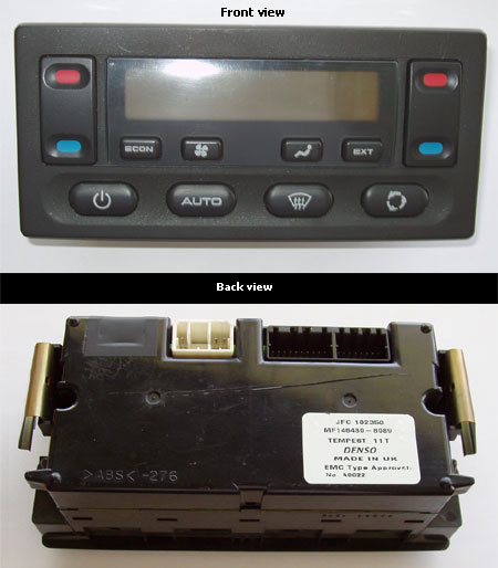
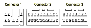
 NIPPON DENSO ATC - Pin Outs