BOSCH EDC - System Overview
The Bosch Electronic Diesel Control (EDC) has long been fitted to most diesel vehicles in one form or another. It is a sophisticated system capable of self detecting many problems. Our software module handles both early and later variations used in the listed applications although many more applications may exist that use a compatible variant.
SM007 - BOSCH EDC - System Help file
Version 1.27

BOSCH EDC - Known Fitments
Vehicle makes, models and variants known or believed to be using this vehicle system, required diagnostic lead and degree of known compatibility.

Vehicle Make Vehicle Model Vehicle Variant Diagnostic Lead
Land Rover Discovery 1996> Black OBDII Lead
  Freelander 1998 - 2001 Black OBDII Lead
  Range Rover (P38) 1994-2002 Black OBDII Lead
Rover 400 ALL Unknown
  600 ALL Unknown
  800 ALL Unknown
  New 200 ALL Unknown
  New 400 ALL Unknown

BOSCH EDC - Physical Details

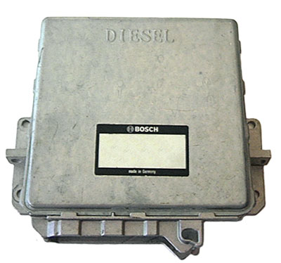
BOSCH EDC - Pin Outs
Details of the pin usage for the ECU connector(s).

 
1 Fuel Quality Solenoid
2 Fuel Quality Solenoid
3 Fuel Cut Off Solenoid
4 Check Engine Warning Lamp
5 Needle Lift Sensor (signal)
6 EGR Solenoid
8 Glow Plug Relay
9 Aircon Active
10 Injector Timing Solenoid
11 Glow Plug Warning Light
12 Sensor Earth
13 Sensor Earth
14 Fuel Quality Feedback Sensor (middle)
16 ECU Positive Feed
17 ECU Positive Feed
18 ECU Earth
19 ECU Earth
21 Fuel Quality Feedback Sensor (reference)
25 Throttle Position Sensor Idle Switch
26 Brake Pedal Switch (1st)
27 Diagnostics (L Line)
29 Speed Sensor
31 Brake Pedal Switch (2nd)
33 Throttle Position Sensor Supply
35 Fuel Temperature Sensor
36 Inlet Air Temperature Sensor
37 Throttle Position Sensor Signal
38 Mass Airflow Sensor
39 Fuel Quality Feedback Sensor (measured)
42 Diagnostics (K Line)
44 Aircon Sense
45 Immobiliser Signal
47 Crank Sensor (signal)
50 Tachometer
51 Boost Pressure Sensor (+VE)
53 Coolant Temperature Sensor
54 Boost Pressure Sensor (signal)

SM007 - BOSCH EDC - Diagnostic Capabilities (Read Fault Codes)
The Electronic Diesel Control (EDC) has a very sophisticated system for logging faults and although it has only 27 fault codes, for each code it logs, there is attached to it a number of flags which give much more information about the fault, thus multiplying the effective number of different events which share the same basic code by many times. There are also two system sensor values, which are stored as a form of freeze frame data giving more information about the circumstances that caused the fault. The data that is captured depends on the fault. Each code read-out of the system is presented, starting with a description of the circuit to which the fault is pertaining, followed by the name of the first value and the value itself, the name of the second value and the value itself, then by a list of the meanings of the flags which have been triggered. The flag options are:

  • TOO HIGH: The value from the sensor in question is / was above accepted limits.
  • TOO LOW: The value from the sensor in question is / was below accepted limits.
  • OPEN CIRCUIT: The sensor in question was not detected in its wiring loop.
  • INVALID VALUE: The value from the sensor in question is / was not a sensible or possible value.
  • MAJOR FAULT: A fault that can prevent the engine from running and requires immediate attention.
  • FAULT LOGGED: A fault which causes no adverse or noticeable affect, but never the less has been seen.
  • CURRENT: Where the fault is actually there now as opposed to having been there and not being there when the fault memory is read.
  • INTERMITTENT: Where the fault in a sensor has been seen and logged on one occasion, then the sensor has been accepted as working OK, and then goes faulty and the cycle repeats.
It is important to remember these 8 attached flags, because they are only listed if they are set and the fact that they are missing will give you as much information as if they are resident, helping you locate the source of the problem. i.e. the fact that the fault is continuously there, is denoted by the absence of the intermittent flag. Important information is a count of the number of times the system has detected the fault on system power up. It is also worth noting that when the vehicle is not fitted with Cruise Control the EDC ECU logs this fact as a fault with the cruise control, which because it is not a major fault is ignored.

SM007 - BOSCH EDC - Diagnostic Capabilities (Clear Fault Codes)
This function first reads the fault code memory to ensure that there are faults to clear and if there are completely erases and clears the fault code memory. Having deleted the faults it then re-checks the fault memory to check that it is clear, reporting success if it is. Failure to clear the fault memory successfully is usually due to the system re-logging the fault the moment the fault memory is clear. This indicates that the fault has not been rectified properly and as far as the system is concerned, still exists. The re-check for successful clearing of the fault code memory may pass but then the system may re-log the fault shortly after.

SM007 - BOSCH EDC - Diagnostic Capabilities (Settings)
Values, configuration settings, and other stored information which can be read from the ECU, edited and then rewritten back. Read settings can also be stored as a standard HTML page for reference. These pages can then later be re loaded and re written back to the ECU. Please note that some values may be read only due to the fact that they are supplied from the ECU’s ROM or are internally calculated.

  • ECU type: Gives the manufacturer's name for the EDC ECU.
  • BOSCH hardware revision: Gives the manufacturer's hardware revision number for the EDC ECU.
  • BOSCH software revision: Gives the manufacturer's software revision number for the EDC ECU.
  • Firmware version: Gives the BMW reference number for this EDC ECU.
  • Subrevision number: Gives the revision number for the firmware of the EDC ECU.
  • Identity number: The unique identity or serial number for this EDC ECU.
  • EMS code: When the ignition is turned on, the Body Control Unit or the programmable Alarm providing it is in receipt of a recent valid mobilization code, i.e. the correct key fob has been pressed, or a correct EKA code has been entered and is therefore, not in an alarmed or immobilised state, will send a coded signal to the EDC ECU, which it then compares against a unique non changeable security code (the EDC code) it has stored in it. If the code received and the code stored compares OK, the EDC allows the engine to start. This forms the basis of the immobiliser. If the EDC ECU, the BCU or the programmable Alarm is replaced, the two codes will not match and it will not be possible to start the engine. It is therefore necessary to synchronise the codes in both the BCU/Alarm and the EDC ECU. This function reads the code from the EDC ECU but since it is not possible to change the code at this end, the code obtained from this function has to be set in the BCU/Alarm which can easily be done in the BCU settings or Security settings sections of the relevant system.
  • Idle value: This value should normally be 128 and may be altered to increase or decrease the idle speed, however, moving this value more than two or three in either direction may have undesirable consequences. We recommend adding or removing only one at a time from the original number and testing the results. If after 3 or 4 have been reached without the required effect being produced, then a problem may exist in the engine management system.
  • Pump value: The later EDC ECUs have the ability to store 15 bytes of information which are used to help the ECU compensate for manufacturing tolerances for the Diesel pump. These are entered into the ECU when the vehicle is made and other than reading the values from the old ECU when replacing the ECU, it is not possible to later find out the correct values if they have been lost or if the Pump itself is being replaced. In these cases, nominal values of 8 for the first digit and 128 for all of the others should be used.

SM007 - BOSCH EDC - Diagnostic Capabilities (Inputs)
Realtime live display of the information the electronic control unit of the selected vehicle system is currently deriving from its input sensors.

FUELLING
  • Start fuel (mg/str): A value in mg/str that is used internally in calculations regarding compensation during starting.
  • Fuel quantity feedback (mg/str): A value measured in mg/str that is used along with the Fuel Quantity and Fuel Quantity compared values for the EDC ECU to calculate fuelling required compensation values and current load conditions.
  • Current fuel quantity (mg/str): The current fuel quantity value, measured in mg/str is, in conjunction with the fuel quantity compared value, also measured in mg/str, an indication of any increase in demand which obviously varies with load. Any increased load on the engine such as heated windscreens or air conditioning compressors will need a compensation for the load. When the load is applied, this value should rise above the fuel quantity comparison value momentarily then drop back below to where it normally is.
  • Fuel quantity compared (mg/str): The fuel quantity compared value, measured in mg/str is, in conjunction with the current fuel quantity Value, also measured in mg/str, an indication of any increase in demand which obviously varies with load. Any increased load on the engine such as heated windscreens or air conditioning compressors will need a compensation for the load. This is the non compensated value.
  • Fuel temperature (°C): The current fuel temperature sensor input value in degrees centigrade. This is used to help the EDC ECU to compensate for hot fuel conditions especially when starting.
  • SWG set point (mV): The current SWG Set Point value over a range of 0 to 5000 millivolts. The SWG is the Control Sleeve Travel sensor. This value is the value which the EDC ECU has determined it should be getting back from the sensor. This value should be below 1,500 millivolts after approximately 20 seconds.
  • SWG actual (mV): The current SWG Actual value over a range of 0 to 5000 millivolts. The SWG is the Control Sleeve Travel sensor. This value is the value which the sensor is giving the EDC ECU.
  • Injector set point degrees: The current Injection SWG set point in degrees over a range of 0 to 25 degrees. The Set point values should be higher when the engine is cold and decrease to 1 or 2 degrees when fully warm, at that point the Timing Modulation should also remain steady at between 45% and 55%.
  • Injector actual degrees: The current Injector Actual value in degrees on a range of 0 to 25 degrees. The Actual value should be within 0.5 degrees of the set point value; at that point the Timing Modulation should also remain steady at between 45% and 55%.
  • Timing modulation (%): This value is the amount of percentage change that the EDC ECU applies to the injection timing, it can be checked in conjunction with the Injection set points and actual values. On a fully warm engine this value should steadily remain between 45% and 55%. There should be no erratic fluctuations.
SWITCHES
  • Idle: The current status of the idle switch attached to the accelerator pedal. This switch should be closed when the Throttle Pot percentage is below 9% and open when the Throttle Pot percentage is above 9%.
  • Low idle: Low idle status as determined by the ECU.
  • Needle (rpm): The Engine's speed as determined from the Needle lift sensor in RPM. This value should never differ from the value obtained by the Crank Speed sensor by more than 40 RPM at idle.
  • Crank speed (rpm): The Engine's speed as determined from the crankshaft sensor in RPM. Used to check correct operation of the Needle Lift Sensor.
  • Road speed (mph): he vehicle's current road speed in miles per hour.
  • Road speed (km/h): The vehicle's current road speed in kilometres per hour.
  • ELAB: The current status of the fuel cut-off valve (ELAB).
  • Alarm status: The current status of the ECU. i.e. if it is not in receipt of a valid EDC code before starting is attempted, it will go into alarm thus inhibiting starting.
  • Primary brake: This shows the state of the uppermost of the two switches that are actuated by motion of the brake pedal. Normally it should indicate low, changing to high as soon as motion is applied to depress the brake pedal.
  • Secondary brake: This shows the state of the lowermost of the two switches that are actuated by motion of the brake pedal. Normally it should indicate high, changing to low towards the bottom of the brake pedal's travel.
  • Aircon requested: When the A/C button is pressed, an active low signal is output to the EDC ECU (The Request). This then looks at factors like engine temperature, load, current acceleration etc. and will, according to when these conditions allow, grant Air conditioning. This involves it engaging the clutch to drive the Air Conditioning pump, altering its internal fuelling to compensate for the load imposed by the pump, managing along with the Hevac the Condenser fans, and also telling the Hevac that Air Conditioning has been Granted. This shows the current status of the request line from the Hevac ECU.
  • Aircon grant: When the A/C button is pressed an active low signal is output to the EDC ECU (The Request). This then looks at factors like engine temperature, load, current acceleration etc. and will, according to when these conditions allow, grant Air conditioning. This involves it engaging the clutch to drive the Air Conditioning pump, altering its internal fuelling to compensate for the load imposed by the pump, managing along with the Hevac the Condenser fans, and also telling the Hevac that Air Conditioning has been Granted. This shows the current status of the grant line to the Hevac ECU.
  • Clutch: The current status of output which drives the clutch pedal.
GENERAL
  • Water temperature: The current Coolant temperature in degrees centigrade, derived from the coolant temperature sensor.
  • Air temperature: The current air intake temperature in degrees centigrade, derived from the air intake temperature sensor.
  • Boost pressure (KPa): The boost pressure sensor measures inlet manifold turbo pressure and is displayed in KPa. It should not vary from the atmospheric value by more than plus or minus 5 KPa when not running or at idle.
  • Atmospheric pressure (KPa): Current Atmospheric pressure measured in KPa, derived from the pressure sensor.
  • Throttle pot (%): The current output from the Throttle position Potentiometer calculated as a percentage.
  • Throttle pot volts: The current voltage output from the Throttle position Potentiometer. Should go below 0.8 volts when the pedal is released and above 3.3 volts when the pedal is depressed.
  • Battery volts: The current supply voltage at the EDC ECU.
  • Low idle value: The current low idle figure determined by the EDC ECU.
  • Cruise status: The currently pressed cruise control buttons derived from the voltage arriving at the EDC ECU. 0.8 to 0.9 = Accelerate/Set button pressed, 1.6 to 1.9 = Resume button pressed, 3.4 to 3.6 = No buttons pressed with the console switch on, 4.1 to 4.3 = console switch off, 5.0 = not installed.

SM007 - BOSCH EDC - Diagnostic Capabilities (Outputs)
Choice of outputs that can be tested. Click on the START link to activate the output for 30 seconds.
  • Force Timing Solenoid: This triggers the timing solenoid which is mounted on the Injector pump. It should be heard ticking.
  • Force ELAB valve: Forces on the fuel shut-off valve (ELAB) for 30 seconds.
  • Flash warning lamp: Flashes the engine malfunction indicator lamp in the instrument cluster to check correct operation and that the ECU has full control.

SM007 - BOSCH EDC - Diagnostic Capabilities (Other)
Choice of functions that can be performed.

  • Set new ECU to robust mode: This function only works on brand new EDC ECUs which are delivered from the factory in a non-configured mode (factory mode), before they can be used on a vehicle they have to be configured to either require a mobilization code before they will work (robust), or to work regardless of any other factor (non-robust). This function sets a brand new EDC ECU to robust mode. It should be noted that this function is only able to be performed once due to a restriction within the design of the EDC ECU itself. It is therefore important that the correct choice is made.
  • Set new ECU to non-robust mode: This function only works on brand new EDC ECUs which are delivered from the factory in a non-configured mode (factory mode), before they can be used on a vehicle they have to be configured to either require a mobilization code before they will work (robust), or to work regardless of any other factor (non-robust). This function sets a brand new EDC ECU to robust mode. It should be noted that this function is only able to be performed once due to a restriction within the design of the EDC ECU itself. It is therefore important that the correct choice is made.
  • Security learn: When used in a Freelander the EDC ECU employs a different method of immobilisation and whilst the normal system used by the New Range Rover and Discovery require the EDC ECU to be in robust mode, requiring a valid EMS mobilisation code to be sent from the BECM or Alarm, which can be read from the EDC settings page. Freelander requires the EDC to be non robust but can learn a code from the CCU which is sent when the ignition is turned on. Therefore when fitting an EDC ECU to a freelander or swapping one from another vehicle this function must be run after ECU installation and immediately after attempting to start the engine without turning off the ignition. After the function has been used re-attempt to start the engine which should then start. If it does not the ignition switch must by turned off then on again.