BOSCH MOTRONIC M5.2.1 - System Overview
Quite a sophisticated Petrol Engine management system. Manufactured by Bosch, this ECU was one of the first Flash memory based ECU’s with a huge memory the entire code that controls it’s operationally and functionality including its self diagnostic capability. It has capability to incorporate and control many additional sub systems such as evaporative control used in LEV (Low Emission Vehicle) applications and Secondary Air injection, although not fitted in all markets. Although used extensively in quite a variety of BMW models and having many other mentions, the system was also fitted as a replacement of the previous Lucas Sagem Gems engine management into the petrol versions of the P38 Range Rover after the 1999 model Re vamp and stayed in service to the end of production. It was also utilised In the V8 variant of the Discover series II. Having CAN bus communication capability, the system co exists with a new auto box control system giving much smoother drivability.

The ECU support the limited degree of information and fault codes provided for by enforced OBDII compliance, but of course there many more fault codes, functions and features that this module gives access to beyond simple OBDII compatibility, including security link learning and re synchronization. The Module also gives access to the diagnostic capabilities provided in the sub systems that are not fitted in all markets.
SM009 - BOSCH MOTRONIC M5.2.1 - System Help file
Version 1.27

BOSCH MOTRONIC M5.2.1 - Known Fitments
Vehicle makes, models and variants known or believed to be using this vehicle system, required diagnostic lead and degree of known compatibility.

Vehicle Make Vehicle Model Vehicle Variant Diagnostic Lead
Land Rover Discovery II ALL Black OBDII Lead
Land Rover Range Rover (P38) 1999> Black OBDII Lead
BMW Assorted Unknown Unknown

BOSCH MOTRONIC M5.2.1 - Physical Details

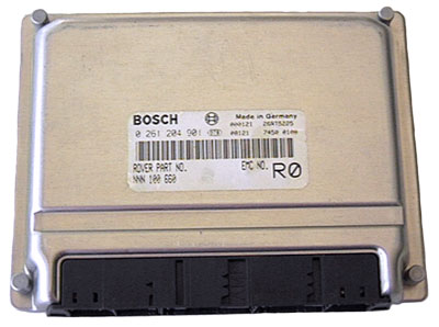
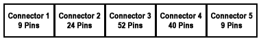
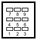
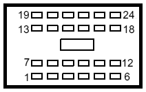
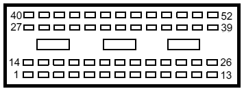
BOSCH MOTRONIC M5.2.1 - Pin Outs
Details of the pin usage for the ECU connector(s).


Connector 1
1 Ignition signal
2, 3 Not Used
4 Ground
5 Ground - Injectors
6 Ground - power stage
7 Battery supply
8 Switched input
9 Not Used

Connector 2
1 Lambda heater bank B - output
2, 3, 4 Not Used
5 Thermostat monitoring thermistor - ground (LEV only)
6 Not Used
7 Lambda heater bank A - output
8 Lambda sensor bank B - ground
9 Lambda sensor bank A - ground
10 Lambda sensor bank B - ground
11 Lambda sensor bank A - ground
12 Not Used
13 Lambda heater bank B - output
14 Lambda sensor bank B - input
15 Lambda sensor bank B - input
16 Lambda sensor bank B - input
17 Lambda sensor bank A - input
18 Fuel pump relay - output
19 Lambda heater bank A - output
20 Not Used
21 Thermostat monitoring thermistor signal - input (LEV only)
22 Not Used
23 Main relay output
24 Not Used

Connector 3
1 Injector Cyl 2 - output
2 Injector Cyl 5 - output
3 Purge valve - output
4 SAI valve solenoid - output (LEV only)
5 Not Used
6 Fuel tank pressure sensor - ground (non LEV only)
7 Air flow meter - output
8 Not Used
9 Air flow meter - ground
10 Throttle pot - output
11, 12, 13 Not Used
14 Injector Cyl 7 - output
15 Injector Cyl 6 - output
16 Not Used
17 Cam sensor - ground
18 Low range switch - input
19 Not Used
20 Camshaft sensor - input
21 Coolant sensor
22 Coolant temperature sensor
23 Air flow meter - input
24 Throttle potentiometer - input
25 Throttle potentiometer - ground
26 Not Used
27 Injector Cyl 3 - output
28 Injector Cyl 8 - output
29 Hill descent control - output
30 Canister vent solenoid - output
31 Air conditioning condenser fan - output
32 Crankshaft sensor
33 Not Used
34 Air temperature - input
35 Knock sensor bank B - ground
36 Knock sensor bank B - input
37, 38, 39 Not Used
40 Injector Cyl 4 - output
41 Injector Cyl 1 - output
42 Idle speed actuator open - output
43 Idle speed actuator close - output
44 Coolant temperature - output
45 Crankshaft sensor screen - ground
46 Crankshaft sensor signal - ground
47 Not Used
48 Knock sensor bank A - ground
49 Knock sensor bank A - input
50, 51, 52 Not Used

Connector 4
1, 2, 3, 4, 5, 6, 7 Not Used
8 Low fuel level - input
9 Fuel tank pressure sensor - output (non LEV only)
10, 11 Not used
12 Analogue fuel level (LEV only)
13 Not used
14 Fuel tank pressure sensor - input
15 Not Used
16 Air conditioning compressor request - input
17 Engine speed - output
18, 19 Not Used
20 Malfunction indicating lamp - output
21 Not Used
22 Road speed
23, 24, 25, 26, 27, 28 Not Used
29 Air-conditioning compressor relay - output
30 Not Used
31 DMTH Heater - output (LEV only, 02my)
32 Diagnostic K-line
33 Immobiliser - input
34 Rough road - input
35 Not Used
36 CAN bus high line
37 CAN bus low line
38 Air conditioning stand by - input
39, 40 Not Used

Connector 5
1 Not Used
2 Ignition drive Cyl 2 and 3 - output
3, 4 Not Used
5 Ignition coil - ground
6 Ignition drive Cyl 1 and 6 - output
7 Ignition drive Cyl 4 and 7 - output
8 Ignition drive Cyl 5 and 8 - output
9 Not Used

SM009 - BOSCH MOTRONIC M5.2.1 - Diagnostic Capabilities (Read Fault Codes)
Reads the fault code memory. The ECU can self detect up to 105 different problems with itself, its wiring and its associated sensors, storing the respective code if it detects any malfunction or reading outside of pre defined acceptable limits. Not all stored faults may cause the fault warning lamp to illuminate.

SM009 - BOSCH MOTRONIC M5.2.1 - Diagnostic Capabilities (Clear Fault Codes)
This function diagnostically clears the fault code memory.

SM009 - BOSCH MOTRONIC M5.2.1 - Diagnostic Capabilities (Settings)
Values, configuration settings, and other stored information which can be read from the ECU. Read settings can also be stored as a standard HTML page for reference. These pages can then later be re loaded.

PROGRAMMABLE OPTIONS (DETAILS)
  • Part number: This number is calculated from the internally stored Bosch Hardware number.
  • Bosch software: This is an internal number which denotes the base software of the ECU. In conjunction with other codes, this helps trace any production problems back to the exact source so that they can be quickly rectified. This code is, therefore, only of use to Bosch in the event of a production / recall problem.
  • Supplier no: This is a Bosch code which they use for keeping track of ECUs which may have been constructed by other companies under licence or the code which may have been written to be included in ECUs.
  • Production no: This is a unique number for each Motronic ECU which is assigned during production. In essence, it is a Bosch serial number.
  • Revision level: This is a number which denotes subtle changes to the base software of the ECU. In conjunction with other codes, this helps trace any production problems back to the exact source so that they can be quickly rectified. This code is, therefore, only of use to Bosch in the event of a production / recall problem.
  • Revision Address: This is a Bosch specific code which helps track the source of base software revision modifications. In conjunction with other codes, this helps trace any production problems back to the exact source so that they can be quickly rectified. This code is, therefore, only of use to Bosch in the event of a production / recall problem.
  • Plant ID: This is a manufacturer's code which allows tracing to a particular manufacturing facility. In conjunction with other codes, this helps trace any production problems back to the exact source so that they can be quickly rectified. This code is, therefore, only of use to Bosch in the event of a production / recall problem.
  • Plant address: This is a manufacturer's code which allows tracing to a particular manufacturing facility. In conjunction with other codes, this helps trace any production problems back to the exact source so that they can be quickly rectified. This code is, therefore, only of use to Bosch in the event of a production / recall problem.
  • Diagnostic index: This code is reserved for denoting any minor revisions to the Diagnostic section of the internal software.
  • ISN address: This is a code which denotes the actual programming machine which was used to program the base software into this ECU. In conjunction with other codes, this helps trace any production problems back to the exact source so that they can be quickly rectified. This code is, therefore, only of use to Bosch in the event of a production / recall problem.
  • BUS index: An unknown internal code for Bosch use only.
  • Product week: The week of the year in which this Motronic ECU was manufactured.
  • Product year: The year in which this Motronic ECU was manufactured.
  • Coding index: This number is reserved to denote any minor revisions to the core coding of the Motronic ECUs.
  • Immobilisation Code: This number is the number which the Motronic ECU requires to be sent by the BECM to mobilize. This code will require programming into the BECM settings Immobilisation Code box.
  • Bosch hardware code: This number is reserved to denote any minor revisions to the actual electronic hardware of this ECU series.
  • Software code: This code denotes the revision level of the vehicle specific code section of the ECU.
  • Part no: This is a Bosch part number for this Motronic ECU. This number is for the ECU as a whole and provides for the including of any later uploaded changes. It is, therefore, possible this number may change during the life of the ECU.
  • Modification code: This code is used to indicate any late modifications which may have been made to the vehicle specific software, as denoted by the Software Code.
HISTORY INFORMATION RECORD 1-14

The ECU can be programmed (reprogrammed) only 14 times. Each time the settings are stored in a record (1-14) and cannot be overwritten).

  • Vehicle identity number: This is the Vehicle Identity Number (VIN).
  • Date of programming: This is the date when this record was created.
  • ECU assembly no: The assembly is defined as a combination of the ECU's hardware, the engine specific software and the vehicle model / market tune software.
  • Emission homologation status: This is a number which correlates to the passing of emission legislation requirements of this ECU assembly.
  • Odometer value at program date: When re-programming is done which creates a record, it is possible for the programming tool to use this value to record the odometer value of the vehicle to which this ECU was fitted in kilometres. This number could be entered manually, or the equipment could automatically obtain the value by reading the figure electronically from the relevant Body Control Module. Its value is only of some use as the ECU may be moved between vehicles.
  • AIF status: This code, whilst contained in all records, is currently not used for any purpose. It is actually filled with the time of day in hours, minutes and seconds when the re-programming that created this record was performed.
  • Programming station: When any re-programming of the Motronic ECU's software for Engine specific code or model / market tune. The programming may be done at a number of stages during the life of the ECU by different programming equipment made by a number. This is a code by which the programming equipment may be recognised. The most common code is T9999; this denotes Land Rovers own TestBook equipment. X codes usually refer to Bosch programming equipment and are often seen in the 1st record which is created during manufacture.

SM009 - BOSCH MOTRONIC M5.2.1 - Diagnostic Capabilities (Inputs)
Realtime live display of the information the electronic control unit of the selected vehicle system is currently deriving from its input sensors.

AIR AND FUELLING
  • MAFS: Air Mass Flow Rate in Kilograms per hour. This reading shows the amount of air which is being used by the engine. Under most conditions this will indicate the current power output of the engine.
  • Injector time: Fuel Injector Pulse width in milliseconds. The value represents the time the fuel injector is open and injecting fuel into the inlet manifold. The value is an average of the time across all injectors. The total amount of fuel injected into the engine also depends on the number of injections.
  • Fuel pump: This reading shows whether the ECU is currently driving the fuel pump relay ON or OFF.
  • Idle air: Amount of air flow due to Idle Air Control Valve (IACV). The reading shows the amount of air being provided to the engine by the idle air control valve. A higher than usual value for idle air may indicate a problem with engine efficiency. A low value may indicate a throttle problem or a severe air leak.
  • IACV drive: Idle Air Control Valve (IACV) drive duty ratio. The reading shows the amount of drive the IACV is requiring to provide the idle air flow. High values of IACV drive with low values of idle air may indicate a blockage or fault with the valve.
  • Idle load air: This shows the amount of air required by the engine at idle. An unusually high value of idle air may indicate a problem with engine efficiency.
  • AV trim bank A: Average value of fuel trim ratio - bank A. The value of short term fuel trim is calculated by the ECU by subtracting the actual value of fuelling required by the engine (measured by the oxygen sensors) from the expected (open loop) value, as stored in the fuelling tune. This display shows an average value for this trim. The value of the trim should normally remain close to 1.0
  • AV trim bank B: Average value of fuel trim ratio - bank B. The value of short term fuel trim is calculated by the ECU by subtracting the actual value of fuelling required by the engine (measured by the oxygen sensors) from the expected (open loop) value, as stored in the fuelling tune. This display shows an average value for this trim. The value of the trim should normally remain close to 1.0
  • Load air: Demand Air Correction Sum in Kilograms per Hour. The amount of air correction the engine requires to achieve the target idle speed when there are extra engine loads present, such as the air conditioning compressor. Over a period of time, the ECU learns how much correction to apply under these conditions. There are no expected value ranges shown for this display.
  • Fuel cut off: This reading shows whether the ECU is currently operating the fuel cut-off strategy. This strategy should normally operate during over-run conditions only.
  • Fuel trim A: Short Term Fuel Trim Ratio - Bank A. The value of short term fuel trim is calculated by the ECU by subtracting the actual value of fuelling required by the engine (measured by the oxygen sensors) from the expected (open loop) value, as stored in the fuelling tune. The values are calculated separately for each bank of the engine. The value is shown as a ratio between 0:1 (maximum enleanment) and 2:1 (Maximum enrichment).
  • Fuel trim B: Short Term Fuel Trim Ratio - Bank B. The value of short term fuel trim is calculated by the ECU by subtracting the actual value of fuelling required by the engine (measured by the oxygen sensors) from the expected (open loop) value, as stored in the fuelling tune. The values are calculated separately for each bank of the engine. The value is shown as a ratio between 0:1 (maximum enrichment) and 2:1 (Maximum enrichment).
  • Idle trim A: This value represents a long term trim on bank A, applied by the ECU to the fuelling. Since this trim is additive its main effect is at idle and low engine load conditions.
  • Idle trim B: This value represents a long term trim on bank B, applied by the ECU to the fuelling. Since this trim is additive its main effect is at idle and low engine load conditions.
  • Multi trim A: This value represents a long term trim on bank A, applied by the ECU to the fuelling. Since this trim is multiplicative it has an effect over the whole power range of the engine.
  • Multi trim B: This value represents a long term trim on bank B, applied by the ECU to the fuelling. Since this trim is multiplicative it has an effect over the whole power range of the engine.
  • Secondary air: This reading shows whether the ECU is currently driving the secondary air pump ON or OFF (only fitted to ULEV vehicles).
  • Adaptive purge: Adaption to short term fuel trim, due to purge. This display shows the amount of correction which has been made to fuel trim due to the excess air or fuel introduced into the engine, due to purge. If the purge canister contains little fuel, the adaption will be greater than 1, if the canister contains a high load of fuel the adaption will be smaller than 1.
  • Purge rate: This reading shows amount of purge that the ECU has calculated is currently required. This will depend on the engine conditions and the amount of fuel load currently in the purge canister.
  • Purge status: This reading shows whether the ECU is currently purging fuel or not.
  • Leak rate: Tank leakage factor. The amount of leakage detected by the ECU during the fuel tank leakage test. The value is displayed as a factor which has a range from 0 to 2 where a higher value shows a greater leakage.
  • Tank pressure: The difference between the fuel tank pressure and atmospheric pressure. A positive value shows that the tank pressure is greater than atmospheric pressure and a negative value that it is less.
  • Filtered fuel tank pressure: Shows the filtered value of fuel tank pressure with short term variations in pressure removed.
  • Fuel enrichment: This display shows the sum of all enrichments applied to a warm engine. i.e. all the enrichments applied apart from start up enrichments. The enrichments include those due to throttle or load variations and other short term enrichments. A permanently high value for this item may indicate a fault.
  • Fuel level: This reading shows whether the ECU is showing that the fuel level in the fuel tank is almost empty or acceptable.
SWITCHES AND STATES
  • Loop status: ECU Fuelling Feedback State. The reading shows whether the ECU is currently operating a closed or open loop fuelling strategy. Closed loop indicates that the ECU is using information from the oxygen sensors to control the fuelling. Open loop indicates that the fuelling is being calculated using the standard engine tune only. The feedback state should normally be closed except during cold engine conditions (just after start) or briefly during certain specific driving conditions.
  • Evap system: This reading shows whether the ECU is currently operating the canister purge system. This system will normally operate during most driving conditions from time to time.
  • Mil lamp: This reading shows whether the ECU is currently driving the MIL ON or OFF.
  • Catalyst test: The test shows whether the readiness flag for ECU catalyst conversion diagnostics is set. This flag is set whenever all catalyst relevant internal diagnostic tests have either detected an error or have completed with no error.
  • Crank phase 1: Crank Wheel adaption for phase 1. For optimum misfire detection the ECU needs to learn about any imperfections in the crankshaft wheel. This adaption is a four stage process and this display shows whether phase 1 has been completed.
  • Crank phase 2: Crank Wheel adaption for phase 2. For optimum misfire detection the ECU needs to learn about any imperfections in the crankshaft wheel. This adaption is a four stage process and this display shows whether phase 2 has been completed.
  • Crank phase 3: Crank Wheel adaption for phase 3. For optimum misfire detection the ECU needs to learn about any imperfections in the crankshaft wheel. This adaption is a four stage process and this display shows whether phase 3 has been completed.
  • Crank phase 4: Crank Wheel adaption for phase 4. For optimum misfire detection the ECU needs to learn about any imperfections in the crankshaft wheel. This adaption is a four stage process and this display shows whether phase 4 has been completed.
  • Crank error: The reading shows the number of times the ECU has encountered a problem with the position of the crankshaft sensor reference mark.
  • Full load: This reading shows whether the ECU has determined that the Purge canister contains a high load of recovered fuel vapour which requires purging.
  • Immobiliser state: This reading shows whether the ECU has immobilised the vehicle or not.
  • Start state: This reading shows whether the ECU is currently operating it's Cranking idle fuelling and ignition strategy. When Starting is active, the ECU will normally operate special strategies to aid vehicle start up. This status should become inactive as soon as the vehicle has started.
  • Condenser fan: This reading shows whether the ECU is currently driving the Aircon condenser fan relay ON or OFF. The condenser fan relay drive is shared with the air conditioning system. Either system can turn the fan on. The display only shows whether the ECU is driving the condenser fan relay, it does not show the actual state of the condenser fan or the relay.
  • Idle state: This reading shows whether the ECU is currently operating it's idle fuelling and ignition strategy. When idle is active the ECU will normally operate the idle speed control strategy to maintain a constant idle speed.
  • Purge canister: The current duty cycle ratio of the canister purge valve. 0:1 represents closed and 0.99:1 represents fully open.
  • Purge test: This reading shows whether the readiness flag for ECU purge system diagnostics is set. This flag is set whenever all purge system relevant internal diagnostic tests have either detected an error or have completed with no error.
  • O2 sensor test: Lambda Sensor Test - This reading shows whether the readiness flag for ECU lambda sensor system diagnostics is set. This flag is set whenever all lambda sensor monitoring relevant internal diagnostic tests have either detected an error or have completed with no error.
  • O2 heating test: Lambda Sensor Heater Test - This reading shows whether the readiness flag for ECU lambda sensor heater diagnostics is set. This flag is set whenever all lambda sensor heater relevant internal diagnostic tests have either detected an error or have completed with no error.
  • Compressor switch: This reading shows whether the ECU is reading the state of the compressor switch as ON or OFF.
  • Compressor: This reading shows whether the ECU is currently driving the air conditioning compressor ON or OFF.
  • Accelerator enrich: This reading shows whether the ECU is currently adding extra fuel due to acceleration. The enrichment will normally only last for a short time.
  • CAN faults: This display shows the number of times the CAN inter ECU communications BUS has been reset. In normal operation, no resets apart from the initial one would be expected.
  • CAN status: This reading shows whether the ECU is currently receiving information on the (Controller Automotive Network) bus line. This signal is used to exchange information between the ECUs fitted to the vehicle. The CAN bus signal will only be inactive due to the presence of a fault in one of the ECUs connected to the CAN bus.
  • Ignition switch: This reading shows whether the ECU is reading the state of the air conditioning switch as ON or OFF.
  • Air con switch: This reading shows whether the ECU is reading the state of the air conditioning switch as ON or OFF.
ROUGHNESS AND TIMING
  • Roughness cylinder 1 to 8: This display shows the current value which the ECU has calculated for the engine running roughness for each cylinder. This value will increase the more unevenly the engine is running. Engine roughness is not displayed if idle.
  • Cylinder misfire 1 to 8: Count of misfire events for each cylinder. When the ECU detects a possible misfire, this count value is increased by one. If the value increases to more than a preset limit within 1000 engine revolutions, a misfire fault is set. If not, the misfire count value will be cleared to 0 and a new count begin. It is normal to expect a certain number of 'false' misfire detections during each count.
  • Ignition advance cylinder 1 to 8: This value shows the ignition timing for each cylinder. The individual cylinder ignition timings should not differ from each other significantly for any sustained period.
  • Ignition advance: This reading shows the average ignition advance over all cylinders and it is affected by engine speed, engine load, change of gear, knock detection, throttle position and coolant temperature. During idle condition this value may continuously vary as the ignition advance is used to stabilise the idle speed.
  • Dwell angle: This reading shows the current value of the ignition dwell angle (the amount of rotation of the engine during which an ignition coil is charging. Since the charging time tends to be constant (it only varies with battery voltage) the reading will increase in proportion to engine speed. An unusually large reading may indicate a problem with battery voltage.
  • Tooth count: This display shows the number of crankshaft sensor wheel edges counted by the ECU. This value will count up extremely rapidly during engine running but can be useful for checking that the crankshaft sensor is correctly connected during cranking. If the engine is cranked this display should count up at a rate of at least 30 counts per second. If this does not happen there may be a problem with the crankshaft sensor or crankshaft sensor circuit.
  • Misfire sum: Summary of misfire events over all cylinders. When the ECU detects a possible misfire, this count value is increased by one. If the value increases to more than a preset limit within 1000 engine revolutions, a misfire fault is set. If not the misfire count value will be cleared to 0 and a new count begun. It is normal to expect a small number of 'false' misfire detections during each count.
  • Knock average: This reading shows an average value for knock correction. If this value is continuously above 0, it may indicate a problem with the knock detection system or the engine.
  • Knock detect: This reading shows whether the ECU is currently operating its knock control strategy by changing the ignition timing and/or fuelling for of one or cylinders.
OXYGEN SENSING
  • Downstream trim bank A: The value of this short term fuel trim is adjusted by the ECU to ensure that the downstream oxygen sensors are switching and the catalyst is operating efficiently. A drift in the value of this trim may indicate a problem with the catalyst or exhaust system. This value is likely to temporarily deviate from 1 whenever a change in engine operating conditions occurs.
  • Downstream trim bank B: The value of this short term fuel trim is adjusted by the ECU to ensure that the downstream oxygen sensors are switching and the catalyst is operating efficiently. A drift in the value of this trim may indicate a problem with the catalyst or exhaust system. This value is likely to temporarily deviate from 1 whenever a change in engine operating conditions occurs.
  • Lambda A output: This value shows the current correction output value of the fuelling feedback system for bank A.
  • Lambda B output: This value shows the current correction output value of the fuelling feedback system for bank B.
  • Upstream shunt voltage: Oxygen Sensor Heater Shunt Voltage - Upstream Sensors - This reading shows the voltage across the shunt resistor in series with the oxygen sensor heater elements for the upstream sensors (two heaters in parallel). This reading allows the heater current to be measured.
  • Downstream shunt voltage: Oxygen Sensor Heater Shunt Voltage - Downstream Sensors - This reading shows the voltage across the shunt resistor in series with the oxygen sensor heater elements for the downstream sensors (two heaters in parallel). This reading allows the heater current to be measured.
  • Upstream O2 heater resistance: Oxygen Sensor Heater Drive - Upstream Sensors - This reading shows the current sensor resistance of the upstream oxygen sensor heaters (two heaters driven in parallel). The resistance value increases with temperature so the amount of heating may be estimated from this reading.
  • Downstream O2 heater resistance: Oxygen Sensor Heater Drive - Downstream Sensors - This reading shows the current sensor resistance of the downstream oxygen sensor heaters (two heaters driven in parallel). The resistance value increases with temperature so the amount of heating may be estimated from this reading.
  • Downstream sensor bank A: Oxygen Sensor Voltage - Downstream bank A - This reading shows the output voltage from the downstream bank A oxygen sensor. This voltage should normally be varying slowly over a period of several seconds. If this voltage is not varying (on vehicles fitted with downstream sensors) there may be a problem with the sensor or with the catalyst. If this is the case a fault flag will almost always be set.
  • Downstream sensor bank B: Oxygen Sensor Voltage - Downstream bank B - This reading shows the output voltage from the downstream bank B oxygen sensor. This voltage should normally be varying slowly over a period of several seconds. If this voltage is not varying (on vehicles fitted with downstream sensors) there may be a problem with the sensor or with the catalyst. If this is the case a fault flag will almost always be set.
  • Upstream O2 sensor bank A: Oxygen Sensor Voltage - Upstream bank A - This reading shows the output voltage from the upstream bank A oxygen sensor. This voltage should normally be varying rapidly over a period of a few seconds or faster. If this voltage is not varying there may be a fault with the fuelling system or oxygen sensors. If this is the case a fault flag will almost always be set.
  • Upstream O2 sensor bank B: Oxygen Sensor Voltage - Upstream bank B - This reading shows the output voltage from the upstream bank A oxygen sensor. This voltage should normally be varying rapidly over a period of a few seconds or faster. If this voltage is not varying there may be a fault with the fuelling system or oxygen sensors. If this is the case a fault flag will almost always be set.
  • Upstream O2 sensor bank A min: Minimum Oxygen Sensor Voltage - Upstream bank A - This reading shows zero until the vehicle has been driven through Drive cycle C. After this the reading shows the lowest value measured from the upstream bank A oxygen sensor during the driving cycle.
  • Upstream O2 sensor bank B min: Minimum Oxygen Sensor Voltage - Upstream bank B - This reading shows zero until the vehicle has been driven through Drive cycle C. After this the reading shows the lowest value measured from the upstream bank B oxygen sensor during the driving cycle.
  • Upstream O2 sensor bank A max: Maximum Oxygen Sensor Voltage - Upstream bank A - This reading shows zero until the vehicle has been driven through Drive cycle C. After this the reading shows the highest value measured from the upstream bank A oxygen sensor during the driving cycle.
  • Upstream O2 sensor bank B max: Maximum Oxygen Sensor Voltage - Upstream bank B - This reading shows zero until the vehicle has been driven through Drive cycle C. After this the reading shows the highest value measured from the upstream bank B oxygen sensor during the driving cycle.
  • O2 bank A period: This reading shows the period time of the upstream oxygen sensor for bank A. This value will vary depending on engine operating conditions. The values for bank A and bank B would normally be similar.
  • O2 bank B period: This reading shows the period time of the upstream oxygen sensor for bank B. This value will vary depending on engine operating conditions. The values for bank A and bank B would normally be similar.
  • Upstream heat status: This reading shows whether the ECU is currently operating the oxygen sensor heaters for the upstream oxygen sensors (two sensors wired in parallel).
  • Downstream heat status: This reading shows whether the ECU is currently operating the oxygen sensor heaters for the downstream oxygen sensors (two sensors wired in parallel).
  • O2 sensor ready: This reading shows whether the ECU has calculated that the correct heater temperature has been reached for the oxygen sensors (two sensors wired in parallel).
  • O2 heater ready: This reading shows whether the ECU has calculated that the correct heater temperature has been reached for the oxygen sensors (two sensors wired in parallel).
  • O2 Ageing status: This reading shows whether the Oxygen Sensor Ageing Diagnostic is currently active.
GENERAL INPUTS
  • Engine speed: This measurement shows the engine speed in rotations per minute. The speed is measured using the crankshaft sensor and sensor wheel.
  • Target engine speed: This measurement shows the engine speed which the idle speed control system will use as its target speed. The idle air control system will increase or decrease the air flow into the engine to achieve this value. The speed is calculated using several factors including coolant temperature and the time from engine start.
  • Road speed: The vehicle road speed shown in kilometres per hour, is measured by the ABS unit and is passed to the speedometer and the Motronic ECU as a series of pulses. The Motronic measures these pulses to calculate the Vehicle Road Speed. The reading should be close to the value displayed on the speedometer.
  • Engine load: This reading shows the value of engine load. This is calculated using the MAFS reading and engine speed. The units displayed are in milliseconds (indirectly related to injection times).
  • Engine torque: This display shows the value of the torque output of the engine as calculated by the ECU.
  • Coolant temperature: This display shows the current temperature in degrees centigrade of the engine coolant.
  • Internal temperature: This display shows the current ECU internal temperature. The measurement is taken using a sensor internal to the ECU. The internal temperature reading will not affect the vehicle engine management in any way.
  • Air temperature: The current temperature in degrees centigrade of the air at the engine air intake.
  • Throttle open: The current percentage opening of the throttle position sensor. This percentage varies with the position of the throttle pedal between close to zero with the throttle closed to about 80% at fully open throttle.
  • Closed throttle: This display shows the percentage throttle opening value which the ECU is currently using to decide if the current throttle position is correct for idle speed control (i.e. closed).
  • Test errors: This display shows the number of diagnostic tests which have been started and have detected an error.
  • Total resets: The ECU cumulative resets count.
  • Unexpected resets: This reading shows the number of times the ECU has been unexpectedly reset (by its internal watchdog or power fail) since the ECU was initialised. If this number increases between switching the ignition on and switching the ignition off then there is a problem with either the ECU itself or (more likely) with the 12V power or ground connections to the ECU.
  • OBD trip count: This displays the total number of diagnostic trips which have been completed by the ECU.
  • Battery voltage: This reading shows the vehicle battery voltage measured directly by the Motronic ECU.
  • Operating time: This display shows the number of hours the ECU has been operated for. This number is cleared to zero if the ECU permanent power supply is lost.
  • Autobox: This reading shows whether the ECU expects the vehicle to have an automatic gearbox fitted.
  • Gearbox range: This reading shows whether the transmission is in high or low range.
  • Gearbox switch: This reading shows whether the ECU is reading the state of the Auto Transmission switch as ON or OFF.
  • ECU fan: This reading shows whether the ECU is currently driving the ECU box fan.
  • Catalyst A: This reading gives a measure of the deterioration of the catalyst on bank A. The value is calculated by using information from both upstream and downstream oxygen sensors. A fault is set when the deterioration reaches the permitted limit. The value will read 0.5 if the catalyst test has not yet taken place - this test requires road or rolling road driving.
  • Catalyst B: This reading gives a measure of the deterioration of the catalyst on bank B. The value is calculated by using information from both upstream and downstream oxygen sensors. A fault is set when the deterioration reaches the permitted limit. The value will read 0.5 if the catalyst test has not yet taken place - this test requires road or rolling road driving.
  • Catalyst: This reading shows whether the ECU expects the vehicle to have a catalyst fitted.
  • Catalyst status: This reading shows the functional status of the catalytic converters.
  • Catalyst conversion test: This reading shows whether the ECU has completed the on board diagnostic test for catalyst conversion. The diagnostic will require the vehicle to be driven through a specified series of conditions before it can be completed.
  • Rough road volts: State of rough road input signal line from ABS ECU. Shows whether the ABS ECU is driving its signal line at ground (0V) or supply (12V) level. In normal operation this signal should be continually changing.
  • Rough road status: State of rough road signal from ABS ECU. This reading shows whether the ABS ECU is indicating that the vehicle is currently driving on a rough road. The PWM rough road signal affects the operation of the misfire detection strategy and will prevent the false indication of misfiring during driving on a rough road.
  • Compensation gradient: Leakage Test Compensation Gradient. This display shows the calculated compensation gradient for the evaporative loss leak test.
  • Decay gradient: Leakage Test Vacuum Decay Gradient. This display shows the measured rate of vacuum decay during the evaporative loss leakage test.
  • Build up gradient: Leakage Test Vacuum Build Up Gradient. This display shows the measured rate of vacuum build up during the evaporative loss leakage test.
  • SAI pump status: This reading shows whether the secondary air system pump is currently on or off. This system is activated to reduce the vehicle emissions during the cold start phase of the engine. The secondary air system should only be active whilst the engine coolant temperature is under 55C.
  • SAI system: This reading shows whether the secondary air system is currently active. This system is activated to reduce the vehicle emissions during the cold start phase of the engine. The secondary air system should only be active whilst the engine coolant temperature is under 55C.
  • SAI solenoid valve: This reading implies the state of the secondary air system based on the state of the solenoid valve.
  • Active leak diagnostic: This reading shows whether the ECU is currently running an active diagnosis of the leakage module system.

SM009 - BOSCH MOTRONIC M5.2.1 - Diagnostic Capabilities (Outputs)

  • Fuel pump relay: This function drives the fuel pump relay ON and OFF. Click on the ON link to start the test and on OFF to end.
  • Electronics box fan: This function drives the electronics fan ON and OFF. Click on the ON link to start the test and on OFF to end.
  • Condenser fan: This function drives condenser fan ON and OFF. Click on the ON link to start the test and on OFF to end.
  • CVS valve: This function drives the CVS valve ON and OFF. Click on the ON link to start the test and on OFF to end.

SM009 - BOSCH MOTRONIC M5.2.1 - Diagnostic Capabilities (Other)

  • Discovery security learn: This function forces the Motronic ECU to learn the incoming code from the BCU in a Discovery Series II as its correct mobilization code.
  • Reset adaptive values: The adaptive values should be reset if any of the following components have been renewed or rectified: fuel injector, lambda sensor, fuel pump, fuel rail, MAFS, inlet manifold, after fixing an air leak or if a new ECU was fitted.