Details of the pin usage for the ECU connector(s).
| C0158 |
 |
| A1 |
Injector 5 |
| A2 |
Not Used |
| A3 |
EGR Modulator |
| A4 |
Not Used |
| A5 |
FT Sensor Earth |
| A6 |
Map Sensor |
| A7 |
ECT Sensor |
| A8 |
Sensor Supply |
| A9 |
HT Pin |
| A10 |
AAP Sensor |
| A11 |
MAF Sensor |
| A12 |
Not Used |
| A13 |
CKP Sensor Positive |
| A14 |
Not Used |
| A15 |
Sensor Earth 5 |
| A16 |
CKP Sensor screened earth |
| A17 |
Sensor Earth 6 |
| A18 |
Sensor Earth 3 |
| A19 |
FT Sensor |
| A20 |
Sensor Earth 2 |
| A21 |
Turbocharger Wastegate modulator |
| A22 |
Injector Common 2 |
| A23 |
Injector Common 1 |
| A24 |
Injector 4 |
| A25 |
Injector 1 |
| A26 |
Injector 2 |
| A27 |
Injector 3 |
| A28 |
Not Used |
| A29 |
Glow Plug Relay |
| A30 |
Sensor Earth 4 |
| A31 |
Not Used |
| A32 |
CAN Negative |
| A33 |
High/Low Ratio switch |
| A34 |
IAT Sensor |
| A35 |
CAN Positive |
| A36 |
CKP Sensor Negative |
| C0658 |
|
| B1 |
Earth 1 |
| B2 |
Earth 4 |
| B3 |
Supply battery voltage |
| B4 |
Cooling fan relay |
| B5 |
Fuel pump relay |
| B6 |
MIL |
| B7 |
Temperature Gauge |
| B8 |
Not Used |
| B9 |
A/C clutch request |
| B10 |
Normally closed brake switch |
| B11 |
Cruise Control SET+ switch |
| B12 |
TP Sensor 1 |
| B13 |
Vehicle Speed |
| B14 |
TP Sensor supply |
| B15 |
Cruise Control Master switch |
| B16 |
Normally open brake switch |
| B17 |
Cruise Control RES switch |
| B18 |
Serial communication link |
| B19 |
Tachometer engine speed |
| B20 |
Not used |
| B21 |
Main Relay |
| B22 |
Supply battery voltage |
| B23 |
A/C Fan request |
| B24 |
Earth 3 |
| B25 |
Earth 2 |
| B26 |
TP Sensor earth |
| B27 |
Supply 2 |
| B28 |
Not used |
| B29 |
A/C Relay |
| B30 |
Glow plug warning light |
| B31 |
Not used |
| B32 |
ABS |
| B33 |
Ignition |
| B34 |
Security code |
| B35 |
Clutch switch |
| B36 |
TP sensor 2 |
 SM010 - LUCAS TD5 (LAND ROVER) - Diagnostic Capabilities (Read Fault Codes) SM010 - LUCAS TD5 (LAND ROVER) - Diagnostic Capabilities (Read Fault Codes) |
| For both ECU types, this function reads the TD5 ECU's fault code memory and displays the meanings of any and all faults that may be found there. The ECU can store any one of over 200 fault codes. There are actually two fault memories that can contain identical faults. One memory is used for currently active faults, meaning the fault is present at that precise point in time, and the other is used for faults which have been logged, meaning the fault has been present on previous power on / self test cycles. The origin of shown faults is indicated in brackets. In most cases faults will be recorded in both memories, meaning that the fault is there now and has been on at least the last power on / self test cycle. If however, a fault is stored in the logged memory only without also being stored in the active memory, this means the fault has been there on previous power on / self test cycles and is not there now, in other words, the problem may have been a one off event or there may be an intermittent problem. A presence only in the active memory means that the fault has only just been detected by the ECU. |
| SM010 - LUCAS TD5 (LAND ROVER) - Diagnostic Capabilities (Clear Fault Codes) |
| For both ECU types, this will clear any faults which are stored in the TD5 ECU's fault code memory. It should be noted that the ECU will instantly re-log any faults which have not been properly rectified meaning that when the fault code memory is re-read the fault will still be listed as if it has not been cleared. It should also be noted that where some options such as air conditioning or cruise control are not fitted, the ECU can show the unused inputs or outputs up as if it were fault although, due to the system being non critical, this will not cause the system's MIL light to illuminate. In this event listed faults relating to unused options can be ignored. |
| SM010 - LUCAS TD5 (LAND ROVER) - Diagnostic Capabilities (Settings) |
Values, configuration settings, and other stored information which can be read from the ECU, edited and then rewritten back. Read settings can also be stored as a standard HTML page for reference. These pages can then later be re loaded and re written back to the ECU. Please note that some values may be read only due to the fact that they are supplied from the ECU’s ROM or are internally calculated.
GENERAL SETTINGS AND INFORMATION
Nearly all of the information is identical for both Flash Programmable and Non Flash Programmable type ECUs; however some information, where indicated, relates differently depending upon the ECU type.
- Injector Grades 1 to 5: This is a 5 digit value which tells the TD5 ECU what grades have been assigned to each injector when it was tested at the factory after manufacture. The TD5 ECU then uses these values to compensate the fuelling in direct relation to the tolerances of the injectors fitted to each cylinder. The first two digits are an offset for the start of injection from nominal within the range of plus or minus .000127 seconds, the second two digits are the same as the first but for the end of injection and the last digit is a measured variance in idle performance.
If the Injector grades are lost or unknown it is possible to read them directly from the injectors themselves as the letters are stamped on the top face of their aluminium cover. However, to access the injectors, it is required to first remove the cam cover. When a code is read from an injector it is actually 5 letters you will get, but due to a change in the letter scheme used on later vehicles, for the last letter which actually has overlapping numerical values, we have chosen to show the real numerical value stored in the TD5 ECU to give our users the ability to program correctly in both schemes.
The valid values for the first digit are: A, B, C, D, E, F, G, H, J, K, L, M and N.
The valid values for the second digit are: B, C, D, E, F, G, H, L, M and N.
The valid values for the third digit are: A, B, C, D, E, F, G, H, J, K, L, M and N.
The valid values for the forth digit are: B, C, D, E, F, G, H, L, M and N.
Please be aware that the value you read with the Vehicle Server and then display is the actual numerical value which is stored in the ECU.
To translate the Alpha code value into the correct numerical value the following conversion can be used:
For scheme 1 (earlier - the early ECU would not store a value higher then 3)
A = 0 or 3
B = 1
C = 2
It should be noted that with our system it is possible to enter a value of 3 in the fifth position. Whilst this is possible other test equipment will not be able to accept this and in this case the character A will be displayed.
For scheme 2 (later)
E = 1
F = 2
G = 3
H = 4
J = 5
K = 6
L = 7
M = 8 or 0
Anything greater than 8 is not a valid value.
Again it is possible to have a value, this time of 0, which other test equipment will not able to accept. In this case the character M will be displayed.
- Temperature gauge: The TD5 ECU has been designed to work with a wide range of possible fitments and options. Many of the input sensors and output controls can be omitted giving many vehicle option, model or market variants. This value indicates if this TD5 ECU has its temperature gauge driving function enabled or not.
- Fuel used: The TD5 ECU has been designed to work with a wide range of possible fitments and options. Many of the input sensors and output controls can be omitted giving many vehicle option, model or market variants. This value indicates if this TD5 ECU has its fuel used output for trip computers and econometers enabled or not.
- MIL lamp: The TD5 ECU has been designed to work with a wide range of possible fitments and options. Many of the input sensors and output controls can be omitted giving many vehicle option, model or market variants. This value indicates if this TD5 ECU has been programmed to operate a Malfunction indicator lamp (MIL) or not.
- EGR modulator: The TD5 ECU has been designed to work with a wide range of possible fitments and options. Many of the input sensors and output controls can be omitted giving many vehicle option, model or market variants. This value indicates if this TD5 ECU has been programmed to control an EGR modulator valve or not.
- Auto box: The TD5 ECU has been designed to work with a wide range of possible fitments and options. Many of the input sensors and output controls can be omitted giving many vehicle option, model or market variants. This value indicates if this TD5 ECU has been programmed to work with an Electronic Automatic Transmission (EAT) or not. A vehicle may have an Automatic Transmission but it may be a non Electronic type which does not communicate with the engine management.
- ECU status: The TD5 ECU can operate in either Robust / secure mode, which means it must receive a valid mobilise code from either an Alarm or the BCU before it will start and run the engine. Or the ECU can operate in Non Robust / insecure mode which means that it will start and run the engine without a valid code being sent first. New ECU's shipped from the factory are sent in new / virgin mode and must have the 'Learn Security Code' function ran on them before they will start and run an engine. Whilst the earlier EDC required the user to pre configure new ECUs by manually choosing Robust or Non Robust modes to match Robust or Non Robust BECM's, the TD5 ECU chooses the correct mode itself whilst it is in the learn mode.
- Cruise lamp: The TD5 ECU has been designed to work with a wide range of possible fitments and options. Many of the input sensors and output controls can be omitted giving many vehicle option, model or market variants. This value indicates if this TD5 ECU has been programmed to drive a cruise control warning lamp in the instrument cluster or not, This should not be confused with the cruise control master on off switch lamp which merely indicates power being applied to the cruise control system.
- EGR inlet: The TD5 ECU has been designed to work with a wide range of possible fitments and options. Many of the input sensors and output controls can be omitted giving many vehicle option, model or market variants. This value indicates if this TD5 ECU has been programmed to work with an EGR inlet throttle valve or not.
- SLABS: The TD5 ECU has been designed to work with a wide range of possible fitments and options. Many of the input sensors and output controls can be omitted giving many vehicle option, model or market variants. This value indicates if this TD5 ECU has been programmed to work with the SLABS system or not. If this option is disabled it will cause ABS drive open load faults.
- Cruise: The TD5 ECU has been designed to work with a wide range of possible fitments and options. Many of the input sensors and output controls can be omitted giving many vehicle option, model or market variants. This value indicates if this TD5 ECU has its cruise control function enabled or not.
- CAN bus: The TD5 ECU has been designed to work with a wide range of possible fitments and options. Many of the input sensors and output controls can be omitted giving many vehicle option, model or market variants. This value indicates if this TD5 ECU has been programmed to utilize its Controller Area Network (CAN) bus or not.
- Pot: The TD5 ECU has been designed to work with a wide range of possible fitments and options. Many of the input sensors and output controls can be omitted giving many vehicle option, model or market variants. This value indicates if this TD5 ECU has been programmed to use a 3 track or 2 track throttle potentiometer. The three track configuration was only introduced after VIN number YA288371 in the Discovery series II and 1A605426 in the Defender. Failure to set this value correctly may result in the ECU being unable to see the application of the accelerator pedal.
- ECU Part number: This is the Land Rover part number for this ECU. This number is not available on early non flash programmable type ECU's.
- ECU configuration map ID: This code is stored in the vehicle variant map data. The code is shown exactly as it is stored with each of the 5 ID letters and 3 revision numbers being duplicated twice. With the duplicates stripped out, the resulting code should match that found in fuel tune map.
- Coding index: This is the value read from the ECU. This feature is not available on early non flash programmable type ECUs.
- Diagnostic index: This is the value read from the ECU. This feature is not available on early non flash programmable type ECUs.
- Radiator fan: The TD5 ECU has been designed to work with a wide range of possible fitments and options. Many of the input sensors and output controls can be omitted giving many vehicle option, model or market variants. This value indicates if this TD5 ECU has a radiator fan under its control or not.
- Auxiliary fan: The TD5 ECU has been designed to work with a wide range of possible fitments and options. Many of the input sensors and output controls can be omitted giving many vehicle option, model or market variants. This value indicates if this TD5 ECU has been programmed for an auxiliary radiator or engine cooling fan. In case of fitting the auxiliary fan to the vehicle and the system is disabled in the ECU settings, it will function normally, but it will not be controlled by the TD5 ECU.
- Clutch switch: The TD5 ECU has been designed to work with a wide range of possible fitments and options. Many of the input sensors and output controls can be omitted giving many vehicle option, model or market variants. This value indicates if this TD5 ECU has been programmed to monitor a clutch pedal switch, obviously this switch will not be fitted on automatic gearbox vehicles which have no clutch pedal.
- Road speed: The TD5 ECU has been designed to work with a wide range of possible fitments and options. Many of the input sensors and output controls can be omitted giving many vehicle option, model or market variants. This value indicates if this TD5 ECU has this option enabled or not and is related to if the vehicle is fitted with the SLABS system which generates a road speed signal shared by other vehicle system ECU's. Further information can be read on this value in the 'Dynamic Input Information road speed' value help.
- Tachometer: The TD5 ECU has been designed to work with a wide range of possible fitments and options. Many of the input sensors and output controls can be omitted giving many vehicle option, model or market variants. This value indicates if this TD5 ECU has been programmed to provide an output for driving a tachometer or not. If this option is enabled without a tachometer being fitted an open load fault will be displayed. This is the case on some Defenders so that the Instrument can be retro fitted and simply needs connecting to the output pin of the ECU to work.
- Air conditioning: The TD5 ECU has been designed to work with a wide range of possible fitments and options. Many of the input sensors and output controls can be omitted giving many vehicle option, model or market variants. This value indicates if this TD5 ECU has been programmed to control air conditioning. If this option has been disabled the ECU will store open load faults for the air conditioning fan and electromagnetic clutch. In case of fitting air condition to the vehicle and the system is disabled in the ECU settings, it will function normally, but it will not be controlled by the TD5 ECU.
- Active engine mounting: The TD5 ECU has been designed to work with a wide range of possible fitments and options. Many of the input sensors and output controls can be omitted giving many vehicle option, model or market variants. This value indicates if this TD5 ECU has been programmed to work with the active engine mounting option.
- Ambient sensor: The TD5 ECU has been designed to work with a wide range of possible fitments and options. Many of the input sensors and output controls can be omitted giving many vehicle option, model or market variants. This value indicates if this TD5 ECU has been programmed to use an ambient temperature sensor or not.
- Turbo waste gate: The TD5 ECU has been designed to work with a wide range of possible fitments and options. Many of the input sensors and output controls can be omitted giving many vehicle option, model or market variants. This value indicates if this TD5 ECU has been programmed to control a turbocharger waste gate solenoid valve or not.
- Fuel temperature: The TD5 ECU has been designed to work with a wide range of possible fitments and options. Many of the input sensors and output controls can be omitted giving many vehicle option, model or market variants. This value indicates if this TD5 ECU has been programmed to use a fuel rail temperature sensor or not.
FUEL TUNE MAP INFORMATION
This is a subsection for the information which is stored in the fuel tune map part of the ECU.
- Fuel tune map ID code: This code is made up from 5 letters followed by 3 numerical digits and is stored in the fuel tune data area. It uniquely identifies this specific fuel tune data map and the vehicle.
For Flash programmable type ECU's the five letters of the fuel tune ID code denote application usage as follows:
1) Engine, S = Storm 5 cylinder diesel engine.
2) Gearbox, V or T = Manual, W or U = Automatic.
3) Model, L = Defender, D = Disco, H = unknown.
4) Tune state D, L, X, N or O denote Tune type.
5) Market, E = European, R = ROW, J = Japan, K = Korean.
For Non flash programmable type ECU's the first five letters of the fuel tune ID code denote application usage as follows:
suhde = DISCOVERY/AUTOMATIC/EUROPEAN
sumdj = DISCOVERY/AUTOMATIC/JAPANESE
surdk = DISCOVERY/AUTOMATIC/KOREAN
suhdr = DISCOVERY/AUTOMATIC/ROW
sthde = DISCOVERY/MANUAL/EUROPEAN
sthdr = DISCOVERY/MANUAL/ROW
suhle = DEFENDER/AUTOMATIC/EUROPEAN
sthle = DEFENDER/MANUAL/EUROPEAN
sttde = DISCOVERY/MANUAL/EUROPEAN
NOSELECT = VEHICLE TYPE/MARKET NOT SET (this should only occur on new ECU's)
For both ECU types the last 3 digits represents a version number.
- Vehicle variant map ID code: This code is made up from 5 letters followed by 3 numerical digits. It uniquely identifies what vehicle variant map the fuel tune map was designed to operate with. When programming maps into an ECU, you should ensure that the vehicle variant map that you select has an ID code which matches this code.
- Emission homologation number: This is the emission control test number (Homologation) which is allocated to the ECU configuration / fuel tune map set by the respective authority.
|
| SM010 - LUCAS TD5 (LAND ROVER) - Diagnostic Capabilities (Inputs) |
Realtime live display of the information the electronic control unit of the selected vehicle system is currently deriving from its input sensors.
FUELLING
- RPM: This shows the engine speed in rpm. The engine speed is derived from the crank sensor (T102) signal.
- Road speed (mph): This shows the vehicle speed in kph. The road speed input signal is supplied by the ABS / SLABS ECU (if fitted) or else by the gearbox via a reed switch. Failure of this input would disable cruise control.
- Road speed (km/h): This shows the vehicle speed in mph. The road speed input signal is supplied by the ABS / SLABS ECU (if fitted) or else by the gearbox via a reed switch. Failure of this input would disable cruise control.
- Battery volts: This shows the vehicle battery voltage level.
- Manifold pressure (KPa): Shows the pressure measured by the pressure sensor mounted into the air intake manifold. Failure of the sensor will result in a default value of 100 KPa being used. Typical values are approximately 100 KPa at sea level with the engine stopped; between 100 - 125 KPa during engine idle conditions. High values of up to 220 KPa indicate when the turbocharger is generating boost (around 3000 RPM).
- Ambient pressure (KPa): Shows the ambient atmospheric pressure as measured by the sensor (T209) mounted in the air cleaner lid.
- Air flow (kg/Hr): This shows the mass airflow into the engine derived from the air flow mass sensor (T115). This sensor is connected to the TD5 ECU by two wires on C0158. These wires are brown / orange on pin 11 which goes to pin 2 of C0149 on the sensor and pink / black on pin 20 which goes to pin 1 of C0149 on the sensor. The value is used by the EGR Control; as EGR increases the airflow reduces. Sensor failure results in a default value of zero.
- Throttle 1 volts: This shows the output voltage from driver throttle pedal potentiometer 1 as read by the TD5 ECU. The voltage reading increases as the throttle pedal is depressed. A fault will be recorded if the sum of the voltages of throttle 1 and throttle 2 do not add up to the throttle supply voltage + or - 10%
- Throttle 2 volts: This shows the output voltage from driver throttle pedal potentiometer 2 as read by the TD5 ECU. The voltage reading decreases as the throttle pedal is depressed. A fault will be recorded if the sum of the voltages of throttle 1 and throttle 2 do not add up to the throttle supply voltage + or - 10%
- Throttle 3 volts: This shows the output voltage from driver throttle pedal potentiometer 3 as read by the TD5 ECU. The 3 Track Throttle Potentiometer configuration is not used on all vehicles and was introduced at VIN Number YA288371 on a Discovery and 1A605426 on a Defender. The selection may be configured in the settings section.
- Throttle supply volts: This shows the regulated supply voltage for the driver throttle pedal potentiometers. The sum of the voltages from driver throttle pots 1 and 2 at any throttle position must add up to within 10% of this voltage or a fault will be recorded.
- EGR modulation duty ratio: This shows the open/close duty ratio of the EGR valve (D164). The valve, which is connected to pin 3 of C0158 with a blue wire and to the valve on pin 2 of C0270, is used to re-circulate exhaust gases to reduce nitrous oxide emissions and combustion noise. The higher the reading, the more EGR. Failure of this modulator would lead to increased smoke emissions and combustion noise.
- EGR inlet duty ratio: This shows the open/closed duty ratio being applied to the EGR inlet throttle (Y160) if fitted. The inlet throttle is used in addition to the EGR modulator (D164) to provide additional exhaust gas recirculation by restricting the inlet airflow, thereby increasing EGR. The control software in the TD5 ECU ensures that the inlet throttle is only driven in conjunction with EGR modulation.
- Turbo wastegate duty ratio: Under turbo boost conditions the duty ratio being applied to the waste gate solenoid (N112) is shown. The higher the duty ratio the less air being bled away from the turbine blades hence the higher the boost pressure.
- Idle speed error (rpm): Displays the difference between the target idle speed the ECU is trying to achieve and the actual idle speed measured by the ECU. With the engine idling, the actual engine idle speed is coolant temperature dependent. Readings greater than + or - 15 rpm would indicate a mechanical problem with engine idle control. Typical values with engine idling are -5 to +5 rpm of the required idle speed.
- Coolant temperature (°C): This shows the coolant temperature as measured by the TD5 ECU. This sensor (T121) is connected to the ECU by two wires, a pink / black wire on pin 18 of C0158 which goes to pin 1 of C0169 on the sensor itself and a pink / green wire on pin 7 of C0158 which goes to pin 2 of C0169 on the sensor. If the sensor fails, a default value of warm is displayed on the temperature gauge. Sensor faults may cause several symptoms including poor starting, fast idle speed, poor fuel consumption and cooling fans running continuously. A typical value with a fully warm engine is 88°C.
- Air inlet temperature (°C): This shows the temperature measured by the TD5 ECU using the air inlet temperature sensor (T116). If fitted, this sensor is connected to the TD5 ECU by four wires on C0158. These wires are green / black on pin 34 which goes to pin 2 of C0567 on the sensor, white / yellow on pin 6, which goes to pin 4 of C0567 on the sensor, pink / black on pin 17, which goes to pin 1 of C0567 on the sensor and pink / purple on pin 8, which goes to pin 3 of C0567 on the sensor. If the sensor is open/short circuit, then a fixed default value of 25°C will be displayed. The inlet air temperature is used by the ECM to adjust the ignition timing at altitude. If the sensor is not operating correctly poor EGR and smoke control could result.
- Fuel temperature (°C): The TD5 ECU has been designed to work with a wide range of possible fitments and options. Many of the input sensors and output controls can be omitted giving many vehicle option, model or market variants. This value indicates if this TD5 ECU has been programmed to use a fuel rail temperature sensor or not.
- Power balancing RPM 1 to 5: In the manufacture of an engine there are unavoidable tolerances which vary. This means that each cylinder's power output relative to the others can be higher or lower than others. This imbalance shows up much more at lower engine speeds such as those encountered at idle. It can make the engine seem lumpy and rough especially under acceleration at low speeds when the power is used. Under normal operating conditions, this factor is compensated for by the cylinder balancing routine built in to the software of the TD5 ECU.
This value shows the adjustments in rpm being applied to individual cylinders by the TD5 ECU to achieve smooth running. With the engine idling, the fluctuations in cylinder speed in rpm from the nominal idle speed can be seen. However, you should note that values outside of the range will be seen if the engine speed is varied suddenly i.e. blipping the throttle.
SWITCHES
- Brake switch 1: This displays the state of the footbrake pedal brake switch 1 as seen by the TD5 ECU. The value should show ON when the Brake pedal is depressed and OFF when the Brake pedal is released.
- Brake switch 2: This displays the state of the footbrake pedal brake switch 2 as seen by the TD5 ECU. This switch is only fitted to vehicles equipped with cruise control. Failure of this switch would disable cruise control. It should show OFF with the Brake pedal depressed and ON when the Brake pedal is released.
- Resume/Off: This displays the state of the steering wheel mounted resume/off switch as seen by the TD5 ECU. When this switch is depressed, if a cruise speed is set, cruise control is disabled. If cruise control is already disabled when this switch is depressed, cruise control will be re-enabled, providing that a valid cruise speed was previously set. The value should show OFF with the resume/off button released, and ON with the resume/off button depressed.
- Set/Accelerate: This displays the state of the steering wheel mounted set/accelerate switch as seen by the TD5 ECU. When this switch is depressed, the cruise speed is set to the current vehicle speed, providing the conditions for cruise are met i.e. brakes released, gear engaged and road speed above minimum cruising speed 28mph (35 kph). If cruise control is already active when this switch is depressed, the required cruising speed is increased by 1mph (1.6kph) increments up to a maximum of 100mph (160kph). The value should show OFF with the set/accelerate button released and ON with the set/accelerate button depressed.
- Transfer ratio: This displays the state of the switch input from the high/low gear ratio selector. When it says HIGH, the high ratio gearing is selected, and when it says LOW, the low ratio gearing is selected. To properly engage low ratio, the vehicle needs to be driven slowly forward whilst selecting LOW ratio.
- Cruise: This displays the state of the cruise master switch as seen by the TD5 ECU. This switch determines whether cruise control can be activated. When the value shows ON, the cruise control is switched on and cruise control can be activated. When the value shows OFF, the cruise control cannot be activated.
- Clutch request: This shows whether the HEVAC ECU is requesting the TD5 ECU to engage the air-conditioning compressor clutch. If the request is OFF, the HEVAC is not requesting the compressor clutch to be engaged. If the request is ON, the HEVAC is requesting the compressor clutch to be engaged.
- Clutch drive: This shows whether the TD5 ECU has been able to respond to a request from the HEVAC ECU to engage the air-conditioning compressor clutch. The TD5 ECU can only engage the compressor clutch if the required engine parameters are within limits. These include for example, engine speed, driver demand, etc. When the value shows OFF, the compressor clutch is not engaged and when it shows ON, the compressor clutch output is being driven to engage the clutch.
- Fan request: This shows whether the HEVAC ECU is requesting the TD5 ECU to turn on the air-conditioning condenser fan. If the request is OFF, the HEVAC is not requesting the condenser fan to be turned on. If the request is ON, the HEVAC is requesting condenser fan operation.
- Fan drive: This shows whether the air-conditioning condenser fan output is being driven. The fan could be turned on either in response to a request from the HEVAC ECU or if the TD5 ECU requires additional cooling of the engine. If the value shows OFF, the condenser fan is not being driven and if it shows ON, the condenser fan is being driven.
- Gear switch: This displays the current state of the park/neutral or drive selection switch in the automatic gearbox. The state is transmitted from the gearbox via the CAN link. Failure of this switch in the drive position would prevent starting of the vehicle. If the vehicle is not fitted with an automatic gearbox, then this value should be ignored.
- Clutch switch: This shows the position of the clutch as determined by the clutch switch. When the value shows ON, the clutch pedal is depressed and when the value shows OFF, the clutch pedal is released. Failure of this switch could disable surge damping which would result in a notable decrease in drivability. Cruise control could also be disabled.
|
| SM010 - LUCAS TD5 (LAND ROVER) - Diagnostic Capabilities (Outputs) |
Choice of outputs that can be tested. Clicking on the button allocated to each output, the vehicle server will send a command to pulse that output. That means that the LED will stay on for a second, the injectors will fire once, and it will be only a pulse to the gauges.
- Air conditioning clutch: This test energizes the output for the control relay of the Air conditioning clutch. The relay should easily be heard clicking once and the clutch should be heard to engage.
- Air conditioning fan: This test energizes the output for the control relay of the Air conditioning fan. If the fan is functioning and connected it will spin shortly and you should therefore ensure it is clear and safe to run this test first.
- MIL lamp: This test energizes the output for the Malfunction Indicator Lamp (MIL). The lamp will flash once.
- Fuel pump: This test energizes the output for the Fuel pump control relay. The relay should easily be heard clicking once.
- Glow plugs: This test energizes the output for the glow plug relay. The relay should be heard clicking once.
- Pulse rev counter: This test sends pulses from the TD5 ECU to the engine revolutions counter or Tachometer mounted in the instrument cluster (if fitted).
- Drive temperature gauge: This test sends signals from the TD5 ECU to the engine coolant temperature gauge in the instrument cluster (if fitted). The dial in this gauge should move towards normal from its current position. Click several times to see the needle moving.
- Turbo waste gate: This test sends pulses from the TD5 ECU to the Turbocharger's waste gate modulator valve / solenoid. The valve should be heard clicking. This ECU controllable valve is not always fitted and communications may error if the test is done on ECU's not equipped with the valve.
- EGR throttle inlet: This test sends pulses from the TD5 ECU to the EGR throttle inlet modulator. The modulator should be heard buzzing. This valve is not always fitted and communications may error if the test is done on ECU's not equipped with the valve.
- Injector 1 to 5: This test sends pulses from the TD5 ECU to the respective injector. If fuel pressure is present in the fuel rail, the injector will fire causing fuel to be released at such high pressure that it can easily penetrate human skin with dire consequences. Therefore, great caution is advised if the Injector to be tested is not properly secured into its mounting.
|
| SM010 - LUCAS TD5 (LAND ROVER) - Diagnostic Capabilities (Other) |
Choice of functions that can be performed:
- Learn security code: When the ignition is turned on, the BCU or Alarm, providing it is in receipt of a valid transmitted Key Fob code and is therefore not in an alarmed or immobilised state, sends a coded data transmission to the TD5 ECU. The TD5 ECU then decodes this data and compares the code contained in it against a mobilisation code it has stored in it. If the two codes compare OK, the TD5 will allow the engine to start. This forms the basis of the immobiliser. If the TD5 ECU, the BCU, or the Alarm is changed, it may be required for the TD5 ECU to re-learn a new mobilisation code. This is done by using this function to put the TD5 ECU into Security learn mode. After setting the TD5 ECU into learn mode it is required to turn off the ignition for 15 seconds, then back on. Receipt and acceptance of a valid code can be verified by viewing the 'Immobilisation Status' in the 'Other' section.
- Check modulator valve: This function checks correct operation of the EGR modulator valve (IF FITTED) by first forcing the EGR modulator valve fully off and taking a reading of the Airflow into the engine and then forcing the EGR modulator on and then taking a reading. The engine needs to be idling for this test. If the vehicle does not have an electronically controlled valve fitted this function will error. With the EGR modulator valve off the Airflow into the engine should be around 500 mg per fire, and with the EGR modulator forced on this value should be less than 330 mg per fire. If the valve is not fitted, this function will error.
- Security mobilization status: The TD5 ECU has much improved capabilities in terms of allowing diagnostic checking of the current status of the security link connection from the Alarm or BCU. This function obtains the status of the link.
- ECU self check: This function forces on all of the diagnostically drivable outputs from the TD5 ECU and checks their status, Then it drives them off and re checks their status again.
|
| SM010 - LUCAS TD5 (LAND ROVER) - Miscellaneous |
|
ECU VARIATIONS
Although looking and functioning identically there are in fact two distinctively different ECU types which have some different diagnostic capabilities. The first and therefore earlier type is referred to as the non flash programmable type. This was replaced in late 2002 with a flash programmable type. Non flash types have part numbers that start with MSB while Flash types start with NNN
- Non flash programmable type ECUs typically have just one vehicle types maps pre-programmed into them by the factory. This means they only have one Vehicle variant / fuel tune code and cannot be set to any other. Sometimes however, they might have more than one code stored inside an ECU or the ability to switch between multiple options for a given type. We believe that up to 6 could be pre installed at the same time. If an ECU does have more than one code pre programmed into it can be told which code to use by changing the code to the one for the configuration that you want. Of course, you need to know what any other codes are that may be installed and then try them in the ECU to see if it changes, meaning it has that map installed. Sometimes the sticker affixed to the edge of the ECU itself, which bears the part number, also shows which vehicle types the ECU can be configured to. But if not, fortunately the code can only be one of a handful and can even be deduced to some degree using the information supplied here as a guide.
- Flash programmable type ECUs have the added ability to have their Vehicle Variation and fuel tune maps re programmed diagnostically, which is available as a separate capability in SM201. They also have an incremental programming history memory which includes information such as the VIN number, date of programming and an assembly number which identifies what an ECU was programmed with.
Although part number information has been provided to help identify which type an ECU is, the easiest way to tell is simply to connect to the ECU and read the programming history. Non flash type ECU's will not support the function and flash types will show you the history including the VIN number.
|
|
 LUCAS TD5 (LAND ROVER) - System Overview
 LUCAS TD5 (LAND ROVER) - Known Fitments
 LUCAS TD5 (LAND ROVER) - Physical Details
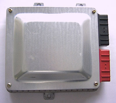