WABCO SLABS - System Overview
This ECU is a very interesting and unusual combination of ABS and Air suspension control within one ECU unit. It would not be so interesting if Wabco did not also produce a range of ECU’s which were visually identical other than being only 2 thirds of the width of this ECU and having only 3 out of the five connectors on them. This ECU is fitted to all Discovery series 2 vehicles regardless of weather they are Air or Coil sprung, and as such the Air suspension can be disabled. The software running inside the system seems to be created using any number of software module components picked to suit each application which may explain why so many visually similar family members have such differing diagnostic communications and features. The ECU has been the subject of several replacement campaigns.
SM016 - WABCO SLABS - System Help file
Version 1.27

WABCO SLABS - Known Fitments
Vehicle makes, models and variants known or believed to be using this vehicle system, required diagnostic lead and degree of known compatibility.

Vehicle Make Vehicle Model Vehicle Variant Diagnostic Lead
Land Rover Discovery II All Black OBDII Lead

WABCO SLABS - Physical Details

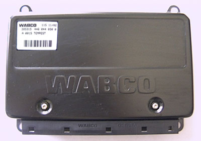
SM016 - WABCO SLABS - Diagnostic Capabilities (Read Fault Codes)
This reads the Self Levelling Anti-lock Braking System (SLABS) ECUs fault code memory and displays the meanings of any faults that it finds there. Faults are listed as Current or Intermittent, together with the number of times the system has detected the fault. The system can detect up too 47 different faults.

SM016 - WABCO SLABS - Diagnostic Capabilities (Clear Fault Codes)
This will clear any faults which are stored in the Self Levelling Anti-lock Braking System (SLABS) ECUs fault code memory.

SM016 - WABCO SLABS - Diagnostic Capabilities (Settings)
Values, configuration settings, and other stored information which can be read from the ECU, edited and then rewritten back. Read settings can also be stored as a standard HTML page for reference. These pages can then later be re loaded and re written back to the ECU. Please note that some values may be read only due to the fact that they are supplied from the ECU’s ROM or are internally calculated.

  • Factory code: This is a Wabco number by which they can identify the production line which built this ECU.
  • Bar code: This is the bar code by which stocks of this ECU can be electronically controlled. The bar code itself and the number it represents can also be found on the outer case of the ECU.
  • Product number: This is a Wabco assigned number which tells them which variation of the same family this ECU is.
  • Product date: This code is used to identify how far into production of this particular variant of this ECU type it was when this individual ECU was built. This would help if a build error was detected and a recall was required.
  • Channel controller: This is a number which identifies the channel controller module for this ECU.
  • Safety controller: This is a number which identifies the safety controller module for this ECU.
  • Diagnostic module: The SLABS ECU is a multi function ECU which manages the functions of; Anti-lock Braking (ABS), Self Levelling Suspension (SLS), Electronic Brake Distribution (EBD), Electronic Traction Control (ETC), Hill Descent Control (HDC) and Electronic Air Suspension (EAS). These different functions all share the same measurements taken from the connected sensors and often control the same valves in conjunction with one another. They also communicate diagnostically as one unit through the same shared connection. This means that each function is treated as a separate module within the ECU, it is possible for any module to be modified independently of the others. For this reason each module has its own reference code by which changes can be traced if required. This is the code for the module which handles self diagnostic checking of all of the other modules.
  • Measurement module: This is the code for the module which manages measuring all of the sensor inputs and supplies the information to all of the other modules. (see details in Diagnostic module).
  • ABS module: This is the code for the Anti-lock Brake System module. (See details in Diagnostic module).
  • EBD module: This is the code for the Electronic Brake Distribution module. (See details in Diagnostic module).
  • HDC module: This is the code for the Hill Descent Control module. (See details in Diagnostic module).
  • Traction control: This is the code for the Electronic Traction Control module. (See details in Diagnostic module).
  • VIN: This is the vehicles unique VIN number.
  • Engine type: This will display the type of the engine: petrol 4.0/4.6 or diesel only when the engine is running. The setting is stored in the SLABS ECU and it cannot be changed.
  • Gearbox: This will display the type of the transmission: manual or automatic only when the engine is running. The setting is stored in the SLABS ECU and it cannot be changed.
  • ECU condition: This is an internal status within the ECU to denote if the ECU is new-born or if it has been configured and is therefore used. When an ECU is sent from the factory it is supplied in the new-born state and besides having the calibration of the height sensors performed requires the VIN and the other running details set up it will need this changing to the USED status too. It is not possible to reverse the status back to new.
  • Test status: This is an internal status which is used to notify the ECU that the SLABS system has been successfully tested or not in the vehicle. Disabled means that the system has not been tested yet and enabled indicates that the system has been checked for correct and safe operation and has passed. This flag must be set by the operator before it is possible to change an ECU's status from NEW to USED. Tests should include verifying that all possible inputs and outputs perform correctly.
  • Transport mode: This is a lock mode for transportation of a vehicle or for work to be carried out.
  • Calibrated: This is an internal status in the SLABS ECU, which is used to note if the stored height settings for the height sensors have been set. On a new-born ECU the value will be no and the ECU knows that the values in the stored height settings are not the correct one. Having used the Store current height function to calibrate the sensors on a new-born ECU, this flag needs to be set to YES to let the ECU know that the calibration has been done.
  • Suspension type: This allows the same ECU to be used for air sprung or coil sprung vehicles. It disables all Air suspension module activity within the ECU and reports no faults to the diagnostic module, even though all air suspension related sensors and valves are missing, effectively transforming the SLABS ECU into a non air suspension ABS ECU. The wiring diagram shows sections for each type of ECU (SLABS & ABS) and the status of this value is the only difference between the two ECU's.
  • Left/Right current height: These are the current heights of the vehicle. In order for the SLABS ECU to know how high a corner of the vehicle is at any given time, it uses a variable resistor which is attached between the vehicle body and hub assembly. The varying value is then put through an analogue to digital converter. This results in a numeric value between 0 and 255 being obtained by the SLABS ECU which represents the relative height of the corner. In real terms, each number is worth approximately 1.4mm of motion. There are, however, certain tolerances in the mounting and design of the suspension and the resistor. This means that on one corner of the vehicle a specific arch height may equate to a different number than the one derived from the same arch height on the opposite corner.
  • Left/Right stored height: It is not possible to read the stored heights. When you read the settings these fields will be filled with N/A. In the fields above you can read the current heights. If you want to change the stored heights, replace N/A with the value you want to change it to. Click on write settings to store the values. Reread settings to see the new current heights.

SM016 - WABCO SLABS - Diagnostic Capabilities (Inputs)
Realtime live display of the information the electronic control unit of the selected vehicle system is currently deriving from its input sensors.

VOLTAGES
  • Pump monitor: This shows the voltage being measured at the ABS pump relay by the SLABS ECU. When driven, the voltage at the pump should be around 2.9 to 3.8 Volts and when not being driven, it should be around 0 to 0.2 Volts.
  • Pump relay: This shows the voltage being applied to the ABS pump relay by the SLABS ECU. When driven, the voltage should be around 2.8 to 3.6 Volts and when not being driven, should be around 0 to 0.5 Volts.
  • Ground reference: This shows the DC value for the reference ground. Expected values are between -0.5 to +1 Volt.
  • Hill descent control brake: This shows the voltage being applied to the Hill Descent Control (HDC) Brake control Relay by the SLABS ECU. When driven the voltage should be around 2.8 to 3.6 Volts and when not being driven should be around 0 to 0.5 Volts.
  • Inlet valve: This shows the voltage being applied to this valve by the SLABS ECU. When driven, the voltage should be around 2.8 to 3.6 Volts and when not being driven, should be around 0 to 0.5 Volts.
  • Outlet valve: This shows the voltage being applied to this valve by the SLABS ECU. When driven, the voltage should be around 2.8 to 3.6 Volts and when not being driven, should be around 0 to 0.5 Volts.
  • Sensor: This shows the DC Voltage for the wheel speed sensor. Expected values are between 2.0 to 2.4 Volts. The wheel speed sensors are different to the conventional wheel speed sensors used on other Land Rover products. Conventionally, wheel speed sensors have an interference fit with the hub or back plate. This positions the sensor close to a reluctor ring. The sensors used on New Discovery series II are incorporated into the inboard wheel bearing, on both front and rear hubs. This bearing assembly is a sealed unit and has no replaceable parts. Also different is the wire from the wheel speed sensor. Land Rover has, historically used a wheel speed sensor employing a signal wire inside a shielded earth wire. The New Discovery series II wheel speed sensors have a twisted pair of wires. This offers some electrical advantages over two straight wires. Such as the signal being less susceptible to electrical noise or interference and it generates less electrical noise, the wires can also be balanced together (similar electrical properties) to ensure voltage losses are minimized. Like a conventional wheel speed sensor, the signal created is an AC sine wave. This wave is generated in the inductive sensor by a sixty-tooth reluctor, machined into the wheel bearing inner race. The frequency of this signal supplies the SLABS ECU with the information it needs to determine the speed of the individual wheels and is used in the calculation of vehicle speed or vehicle reference speed.
  • Rear left/right sensor supply: This shows the voltage of the left/right rear height sensor supply. Expected values are 4.7 to 5.6 Volts.
  • Left/Right valve voltage: This is the voltage measured at the left/right rear air suspension valve.
  • Compressor relay: This is the voltage measured at the air suspension compressor / control.
  • Exhaust valve: This is the voltage measured at the air suspension's exhaust valve.
  • Internal ECU supply: This shows the SLABS ECUs internal supply voltage.
  • Battery voltage: This is the current battery voltage being supplied to the SLABS ECU.
SWITCHES SPEED AND VALUES - The inputs will change if the vehicle is moving. Open the inputs page, and then start the engine. Drive the vehicle at a low speed. Once the speed of 8km/h was reached for all four wheels, the communication will stop.
  • Height left sensor value: This shows the current height value of the rear left air suspension height sensor. A value of 1 is equal to approximately 1.4 mm between the wheel arch and ground.
  • Height right sensor value: This shows the current height value of the rear right air suspension height sensor. A value of 1 is equal to approximately 1.4 mm between the wheel arch and ground.
  • Front left wheel speed: The wheel speed in Km/h. The SLABS ECU cannot detect wheel speeds less than 1.8 KPH. The wheel speed sensors are different to the conventional wheel speed sensors used on other Land Rover products. Conventionally, wheel speed sensors have an interference fit with the hub or back plate. This positions the sensor close to a reluctor ring. The sensors used on New Discovery series II are incorporated into the inboard wheel bearing, on both front and rear hubs. This bearing assembly is a sealed unit and has no replaceable parts. Also different is the wire from the wheel speed sensor. Land Rover has, historically used a wheel speed sensor employing a signal wire inside a shielded earth wire. The New Discovery series II wheel speed sensors have a twisted pair of wires. This offers some electrical advantages over two straight wires. Such as the signal being less susceptible to electrical noise or interference and it generates less electrical noise, the wires can also be balanced together (similar electrical properties) to ensure voltage losses are minimized. Like a conventional wheel speed sensor, the signal created is an AC sine wave. This wave is generated in the inductive sensor by a sixty-tooth reluctor, machined into the wheel bearing inner race. The frequency of this signal supplies the SLABS ECU with the information it needs to determine the speed of the individual wheels and is used in the calculation of vehicle speed or vehicle reference speed.
  • Off road switch: This shows the current status of the SLABS ECUs off road switch input.
  • Hill descent control switch: The state of the Hill Descent Control switch input on the SLABS ECU.
  • Neutral switch: The state of the neutral / transmission switch input of the SLABS ECU. This input should never indicate GND on a manual gearbox equipped vehicle.
  • Differential lock switch: This shows the state of the Differential Lock input on the SLABS ECU. Manual engagement of the Differential Lock can only be done from under the vehicle. ABS is disabled, and the ABS warning light remains on, while the Differential Lock is engaged.
  • Reverse: The state of the Reverse Gear switch input of the SLABS ECU.
  • Shuttle: The modulator houses two shuttle valves, which are moved when brake pressure is supplied via the brake master cylinder's dual channels. The shuttle valves have a switch attached to them, along with a set of resistors located between them. The resistance of the circuit controlled by these shuttle valve switches will change depending upon the position of the shuttle valve. With no brake pressure supplied, the current flows through the three resistors. With one switch open, the current flows through two of the resistors, and when both are open it will flow through only one. The switches can switch at slightly different times because of the internal workings of the master cylinder. The signal from the shuttle valve is used by the SLABS ECU to detect the correct operation of the brake master cylinder and the integrity of the braking circuit, and is used to supply a brake on(tm) signal. The vehicle still has a brake light switch. This switch is used to control the brake lamp operation and the cruise control inhibitor. This shows the state of the shuttle switches input on the SLABS ECU. Valid states are:
    • OPEN CIRCUIT: Which means that either the wiring harness or the switches are faulty.
    • BOTH OPEN: Means that the brake pedal is released and the hydraulics are under HDC/ETC control.
    • ONE CLOSED: Can possibly be shown during transition states or under light braking conditions.
    • BOTH CLOSED: Indicates that the Brake pedal is depressed and the hydraulics are under ABS control.
    • SHORT TO GROUND: Indicates that either the harness or the switches are faulty.
  • Low range: Shows the state of the Low Range switch input line to the SLABS ECU. To change from low to high range you must ensure that the brake pedal is depressed, and neutral gear is selected.
  • Any door ajar: This shows the current status of the door switch input of the SLABS ECU. The ECU inhibits motion of the vehicle if any door is detected as being open.
  • RPM: This shows the engine current number of Revolutions Per Minute. The SLABS ECU cannot detect engine RPMs of less than 300. This means that any value below 300 RPM should be read as 0.
  • Throttle angle deg: This is the deflection of the throttle pedal measured in degrees.
  • Plip signal: This shows the current status of the plip input line to the SLABS ECU from the BCU. The states are:
    • GROUND: the signal line has been detected as being shorted to ground which is a fault.
    • LOWER: this means that the BCU is currently sending a request to lower the vehicle.
    • NEUTRAL: this means that the signal line is normal with no height change requests being made.
    • RAISE: this means that the BCU is currently sending a request to raise the vehicle.
    • OPEN CIRCUIT: The signal line is detected as being open circuit and is therefore faulty. If the signal line is shorted to battery supply voltage this will also be shown as open circuit.
  • Engine torque (Nm): This shows the current engine torque in Newton meters.

SM016 - WABCO SLABS - Diagnostic Capabilities (Outputs)
Choice of outputs that can be tested. Each output has an ON and OFF choice. Click on the ON link to start the test and on OFF to end.

  • Instrument cluster lamps: choice of turning on and off the output to the BCU which signals it to illuminate a selection of lamps.
  • SLS lamp: The SLS system has two information lamps in the instrument pack. Situated in the bottom left of the instrument pack is the first amber warning lamp. If it is continuously illuminated, this indicates that a malfunction has been detected or that the transit function is set. If it flashes, then the remote handset function is being used or the transit function is raising the rear suspension.
  • Off road warning lamp: This amber warning lamp is situated in the top right of the instrument pack. The warning lamp, if continuously illuminated, indicates that the self levelling suspension is in off-road mode. If the lamp flashes, this indicates that the SLS is between the standard ride height and the off-road mode, or that the vehicle is in its extended mode.
  • Traction control lamp: The ETC system employs one amber lamp, which has the letters TC in a dotted circle. The lamp will illuminate during the ignition on lamp check. The system will indicate traction control operation by illuminating the TC lamp for a minimum of 2 seconds.
  • ABS warning lamp: The ABS warning lamp is an amber light with the letters ABS inside a circle.
  • HDC warning lamp: This lamp is used by the HDC system to indicate that the system is switched on and ready to assist with descents, when necessary.
  • HDC fault lamp: The HDC amber lamp is used to indicate a fault with the system. The graphic is the same as the green HDC light, but has an additional exclamation mark next to it. The moment a fault appears that will affect the operation of the HDC function, a audible warning is sounded, similar to the ABS fault warning, and the amber light will be illuminated.
  • Brake warning lamp: The brake or EBD lamp is a combined warning lamp with the low brake fluid warning and the handbrake warning lamp. The lamp is a red light with an exclamation mark inside a brake symbol. The SLABS ECU will illuminate this light if it senses a fault that will affect its ability to control the braking balance of the vehicle.
  • ABS valves: possibility of turning on and off the output of the ABS valves.
  • SLS valves: possibility of turning on and off the output of the SLS valves.
  • Air suspension compressor: this allows the Air Suspension compressor output to be turned on and off.
  • SLS buzzer: this turns on and off the output to the BCU which signals it to sound the SLS buzzer.
  • ABS pump relay: This turns on and off the ABS pump relay output.
  • Speedometer: This drives the speedometer output to simulate 100 Miles per hour.
  • Brake lights relay: This function causes the SLABS ECU to energize the rear brake light relay. This will cause the rear brake lights to illuminate.

SM016 - WABCO SLABS - Diagnostic Capabilities (Other)
Choice of functions that can be performed:
  • ABS power bleed: This function opens all of the ABS valves and powers the pump causing fluid to circulate around the system, thus removing any trapped air bubbles.
  • ABS modulator bleed: This function opens the abs modulator valve and powers the pump causing fluid to circulate around the modulator system, thus removing any trapped air bubbles.
  • Raise left hand rear: This function causes the SLABS ECU to energise the rear left corner valve and the inlet valve. If there is pressure in the system the rear left hand corner will raise.
  • Lower left hand rear: This function causes the SLABS ECU to energise the rear left corner valve and the exhaust valve. This will cause the rear left hand corner to lower.
  • Raise right hand rear: This function causes the SLABS ECU to energise the rear right corner valve and the inlet valve. If there is pressure in the system the rear right hand corner will raise.
  • Lower right hand rear: This function causes the SLABS ECU to energise the rear right corner valve and the exhaust valve. This will cause the rear right hand corner to lower.
  • Store heights: This function sends a command to the SLABS ECU to store the actual heights.