WABCO C TYPE (DISCO I) - System Overview
This family of ABS ECU's, denoted C type, have common characteristic in the diagnostic element of their design. This is that once they have been communicated with diagnostically and then put to sleep they inhibit the communication with other ECUs sharing the same data bus and even with themselves. To re-establish diagnostic communication, the ignition must be turned off for approximately five seconds.

It is only possible to communicate with the ABS ECU when the system is in its idle state, that is with the ignition on and the engine running or not. Once the ECU has detected a signal from all sensors that indicates each one has exceeded 2km/h the ECU turns off the dash lamp and exits diagnostic mode. All ECU resources are then used to monitor the sensors and diagnostic communication is no longer possible until the ignition supply has been disconnected and then re-connected.

Despite sharing a common communication standard which means they all start communicating the same, and share some very basic features, these ECU’s are actually laid out very differently in respect of their memory usage meaning codes read from one ECU with the wrong program may give incorrect meaning and other codes may not be shown. Also some of them actually require each memory location used for the fault code storage to be re programmed to 0 individually. This means that using the wrong module on an ECU can alter the ECU and make it non functional, re using the right module after will not correct this. So although the ECU’s look identical to that used in other vehicles of the same age and can be plugged in, they are NOT diagnostically interchangeable.
SM020 - WABCO C TYPE (DISCO 1) - System Help file
Version 1.27

WABCO C TYPE (DISCO I) - Known Fitments
Vehicle makes, models and variants known or believed to be using this vehicle system, required diagnostic lead and degree of known compatibility.

Vehicle Make Vehicle Model Vehicle Variant Diagnostic Lead
Land Rover Discovery 1996> Black OBDII Lead

WABCO C TYPE (DISCO I) - Physical Details

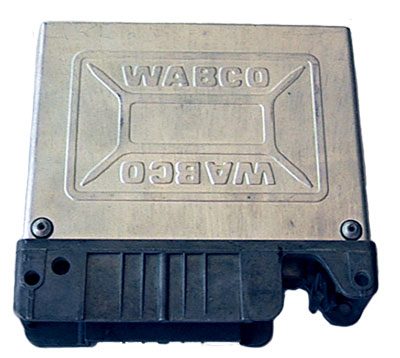
WABCO C TYPE (DISCO I) - Pin Outs
Details of the pin usage for the ECU connector.

 
1 ABS Load Relay
2 ETC Valve Block
3 Instrument Cluster
4 ABS Booster Unit Right Rear
5 ABS Booster Unit Right Rear
6 ABS Booster Unit Right Front
7 ABS Booster Unit Right Front
8 ABS Load Relay (coil)
9 Satellite Fusebox
10 Stop Lamp Switch
11 Isolation
12 Isolation
13 ABS Diagnostic Connector
14 ABS Diagnostic Connector
15 Left Front Wheel Speed Sensor
16 Right Front Wheel Speed Sensor
17 Right Front Wheel Speed Sensor
18 Left Rear Wheel Speed Sensor
19 ABS Load Relay
20 ETC Valve Block
21 ABS Booster Unit Left Rear
22 ABS Booster Unit Left Rear
23 ABS Booster Unit Left Front
24 ABS Booster Unit Left Front
25 Stop Lamp Switch and Suppressor
26 Instrument Cluster
27 ABS Diagnostic Connector and Ground
28 - 29 Not Used
30 ABS Pressure Switch Unit
31 Brake Fluid Level Switch
32 Left Front Wheel Speed Sensor
33 Right Front Wheel Speed Sensor
34 Right Front Wheel Speed Sensor
35 Left Rear Wheel Speed Sensor

SM020 - WABCO C TYPE (DISCO I) - Diagnostic Capabilities (Read Fault Codes)
Each ABS system can self-detect up to 64 faults. These are an even mix of major faults which are safety related, causing full system shutdown and the warning light to illuminate and minor faults caused by flat batteries, power having been temporarily lost.

SM020 - WABCO C TYPE (DISCO I) - Diagnostic Capabilities (Clear Fault Codes)
This function first reads the fault code memory to ensure that there are faults to clear and if there are completely erases and clears the fault code memory. Having deleted the faults it then re-checks the fault memory to check that it is clear, reporting success if it is. Failure to clear the fault memory successfully is usually due to the system re-logging the fault the moment the fault memory is clear. This indicates that the fault has not been rectified properly and as far as the system is concerned still exists. A re-check for successful clearing of the fault code memory may be successful but then the system may re-log the fault shortly after.

SM020 - WABCO C TYPE (DISCO I) - Diagnostic Capabilities (Settings)
Values, configuration settings, and other stored information which can be read from the ECU, edited and then rewritten back. Read settings can also be stored as a standard HTML page for reference. These pages can then later be re loaded and re written back to the ECU. Please note that some values may be read only due to the fact that they are supplied from the ECU’s ROM or are internally calculated.

  • ECU manufacturer: The manufacturer of the ABS /ETC ECU.
  • ECU serial number: This function obtains the electronic identity of ECU'S for record keeping purposes. This number is also printed on a label on the top of the ECU.
  • ETC: This shows if Electronic Traction Control is fitted or not fitted to the ABS system.
  • Coding Data: A specific block of programmable data stored in the ECU to control its functionality for specific variations of vehicle. There are a number of hexadecimal digits, each digit separated by a comma. Re-entered parameters should be entered in an identical format to that which is read. Changing this values can produce unknown alteration in the functionality of the ECU, damage the ECU, or even damage your car.

SM020 - WABCO C TYPE (DISCO I) - Diagnostic Capabilities (Inputs)
Realtime live display of the information the electronic control unit of the selected vehicle system is currently deriving from its input sensors. The ECU will stop communicating at a speed over 1.6mph (2km/h).

  • Wheel speed sensor: This value allows you to monitor wheel speed, which is determined by the ABS ECU measuring the wheel rotation sensor's output. Since the basic principle of ABS relies on comparison between the rotations of all the vehicle's wheels, it is important to be able to see what the system is detecting from the wheels. Jacking up a wheel and rotating it by hand whilst someone prods and moves the associated sensors, connectors and cabling will soon show if a sensor is not working or is intermittent.
  • ABS option code: This value is obtained depending on which valves are fitted to the ECU. It will change if a normal valve is absent or if ETC function valves have been omitted. It can be used to help determine if a vehicle has Traction Control or not.
  • Pressure valve: This value, whilst no direct comparison to known pressure units, is however derived from the pressure in the ABS systems fluid reservoir.
  • Brake switch 1: This shows the state of the upper-most of the two switches that are actuated by motion of the brake pedal. Normally it should indicate low, changing to high as soon as motion is applied through depressing the brake pedal.

SM020 - WABCO C TYPE (DISCO I) - Diagnostic Capabilities (Outputs)
Choice of outputs that can be tested.

  • Fault warning lamp: It is a test to check that the lamps are under the control of the ECU and that the circuit works. Click on ON to turn the ABS lamps and Valve on, and on OFF to extinguish them.

SM020 - WABCO C TYPE (DISCO I) - Diagnostic Capabilities (Other)
Choice of functions that can be performed.

  • Demanual valve: The test works only when performed on vehicles fitted with Electronic Traction Control (ETC) The test is engaging the demanual valve which blocks from the rest of the system any pressure generated from depressing the brake pedal, effectively blocking the manual braking element from the system prior to engaging the computer controlled element. If pressure is applied on the pedal during the test it should be possible to feel the action of the valve feed back on pedal pressure.
  • Isolate ABS inlet/outlet: This test engages the outlet isolating valve. In conjunction with the inlet isolating valve and controls flow between the master cylinder, the servo cylinders, and the reservoir return. If pressure is applied to the brake pedal during the test the pedal should be felt dropping in stages

SM020 - WABCO C TYPE (DISCO I) - Miscellaneous
As well as communicating through its diagnostic data bus, the Wabco type 2 ECU has the ability to output the fault codes through a sequence of flashing. Following the steps described in read fault code page, the ECU can be accessed. The fault codes stored will be displayed by a sequence of flashing of the ABS warning lamp. The fault codes are obtained by counting the flashes. Not all the faults stored in the ECU memory can be read with this method. A maximum of 56 faults can be displayed, while connecting the server to the diagnostic information data bus connector, all the information contained in the fault code memory will be received (74 faults maximum in this case). The codes received with the flash method, although represents the same faults, can be different than the codes displayed when read through the vehicle server.