Values, configuration settings, and other stored information which can be read from the ECU, edited and then rewritten back. Read settings can also be stored as a standard HTML page for reference. These pages can then later be re loaded and re written back to the ECU. Please note that some values may be read only due to the fact that they are supplied from the ECU’s ROM or are internally calculated.
Clicking on the settings link, it will open a page with two choices, "Settings and Information" and 'Coding Data". The first page contains information about BCU ECU, and gives the possibility to change different settings of the body control. The second page contains only coding data, and is to be used only to program a new ECU.
CODING DATA
- Coding Data: A specific block of programmable data stored in the ECU to control its functionality for specific variations of vehicle. There are a number of hexadecimal digits, each digit separated by a comma. Re-entered parameters should be entered in an identical format to that which is read. Changing this values can produce unknown alteration in the functionality of the ECU, damage the ECU, or even damage your car.
SETTINGS / INFORMATION
- Daytime running lamps: Legislation in some markets requires that the headlamps illuminate whilst the vehicle is moving, or the ignition is switched on. This function is referred to as "daylight running lamps". Therefore, the BCU, which controls illumination of the headlamps, must also be programmed to accommodate the legislative requirements of individual markets, with regard to daylight running lamps. The options are:
- The vehicle does not require the daylight running lamp feature to operate in any circumstance (NOT FITTED).
- The daylight running lamps will be on if the main beam head lamps are off (NO MAIN).
- The daylight running lamps will be on whenever the main or dipped beam head lamps are switched ' off' and the gear selector lever is in any position other than ' park' (ALWAYS).
- Shift interlocks: Certain market legislations require that an vehicle must be in neutral or park before removal of the ignition key is allowed, the BCU therefore, is able to be programmed to control solenoids for this purpose. Available options are:
- The vehicle is not fitted with a shift interlock solenoid (NOT FITTED).
- The vehicle is fitted with both shift interlock and transfer box interlock solenoids (BOTH).
- The vehicle is fitted with a shift interlock but no transfer box interlock solenoid (SHIFT ONLY).
- Programmed wash wipe: The front wash switch is located on the wiper stalk, the rear wash switch is located in the instrument pack surround. They are both momentary switches (do not stay in when released). The way the vehicle reacts to the driver pressing the front or rear windscreen wash switch depends upon this setting programmed within the BCU. There are two options:
- No wiper operation when the wash switch is pressed (NO WIPE).
- Wiper action after an initial delay of 400mS (WIPE).
- Seat belt warning lamp: This setting controls operation of the seat belt warning lamp to suit legislative market requirements. Available options are:
- The warning lamp is on for 6 seconds after ignition warning lamp is turned on (TIMED).
- The warning lamp is on for 6 seconds after ignition is turned on or until the buckle is fastened (BUCKLE).
- If the buckle is unfastened when the ignition is turned on then the lamp is on for 6 seconds (IGNITION II).
- The warning lamp is not used (DISABLED)..
- Seat belt warning sound: This setting controls operation of the seat belt warning sounder to suit legislative market requirements. Available options are:
- The warning lamp is on for 6 seconds after ignition warning lamp is turned on (TIMED).
- The warning lamp is on for 6 seconds after ignition is turned on or until the buckle is fastened (BUCKLE).
- If the buckle is unfastened when the ignition is turned on then the lamp is on for 6 seconds (IGNITION II).
- The warning lamp is not used (DISABLED).
- Odometer warning: The BCU can be programmed to show an error if there is a difference between the odometer values stored in the BCU and the Instrument pack. Available options are:
- The odometer will not flash if there is an odometer error (DISABLED).
- The odometer will flash if there is an odometer error (ENABLED).
- Bulb failure warning: The BCU can be programmed to detect failure of one of the direction indicator bulbs, this setting allows the function to be enabled or disabled.
- Autographics: The BCU can be programmed to change the situations in which the automatic gearbox selector leaver illumination (AUTOGRAPHICS) is enabled. The automatic gearbox selector illumination can be on whenever the ignition is on (ALWAYS option) or it can be on when the ignition is on and the sidelights are on (SIDELIGHTS option).
- Low battery warning: If this setting is set to enabled, the BCU will alert the driver of the vehicle if the remote transmitter battery requires replacing. The remote transmitter measures its battery voltage and when the voltage goes below a threshold it will transmit a special code to the BCU to request that it informs the driver by flashing the LED on-off-on short flashes of 50mS and "off" for 2000mS. This is conditional upon the driver's door being open and the ignition in an "off" position, or the key removed from the ignition barrel.
- Front fog lights: In cases where front fog lamps are fitted, the BCU controls their operation via the IDM. The operation of the front fog lamps is therefore programmable, to accommodate the legislative requirements of individual markets. The options are:
- The vehicle is not fitted with front fog lamps (NOT FITTED).
- The front fog lamps operate when the headlamps are dipped or are on main beam (MAIN).
- The front fog lamps will not operate if the headlamps are on main beam (NO MAIN).
- Courtesy headlights: The BCU can be programmed to turn on the vehicle headlamps when the driver presses the remote transmitter. The BCU switches both headlamps on by signalling to IDM to switch the headlamp relay ON.
- Key in warning: If the key is left in the ignition and the driver door is open, a warning sound is generated. This can be disabled or enabled.
- Front windows cancel: The BCU can be programmed to disable operation of the front windows to conform to differing market legislative requirements. Available options are:
- The front windows will be disabled 44 seconds after the driver door is opened (DRIVER).
- The front windows will be disabled 44 seconds after any door is opened (ANY).
- The front windows will be disabled when the ignition is turned off (IGNITION II).
- Rear windows cancel: Although the rear windows and sunroof are controlled by a hard-wired circuit, the rear windows and sunroof ECU are enabled by the BCU. This allows programming of the BCU to disable these outputs to conform to differing market legislative requirements. Available options are:
- The rear windows and sunroof will be disabled 44 seconds after the driver door is opened (DRIVER).
- The rear windows and sunroof will be disabled 44 seconds after any door is opened (ANY).
- The rear windows and sunroof will be disabled when the ignition is turned off (IGNITION II).
- Inertia switch: The inertia switch is located on the bulkhead under-bonnet. It is wired in series with the main relay. Whenever the inertia switch is tripped by a sudden deceleration of the vehicle (over and above the capacity of the braking system), the main power feed to the ECM will be interrupted. This action will stop the fuel pump and the engine by means of the ECM no longer operating the injectors. The vehicle will not restart until the inertia switch has been reset. When the inertia switch has been operated, this setting will affect if the hazards are turned on. Available options are:
- Operation of the inertia switch does not operate the hazard indicators (NO HAZARDS).
- Operation of the inertia switch does operate the (Hazards).
- Engine type: This sets the instrument pack for a Diesel or Petrol vehicle.
- ACE: This configures the instrument pack to indicate the ACE lamp during initial bulb checking and during usage.
- SLS: This configures the instrument pack to indicate the SLS lamp during initial bulb checking and during usage.
- HDC: This configures the instrument pack to indicate the HDC lamps during initial bulb checking and during usage.
- Traction control: This configures the instrument pack to indicate the electronic traction control lamp during initial bulb checking and during usage.
- Gearbox: This configures the instrument pack for either Automatic or Manual vehicles, and then on the second choice, configure the BCU for either Automatic or Manual.
- Police: This setting is used to configure the instrument pack for Police force vehicles. It's operation on non Police specification instrument packs is unknown.
- Gulf: This setting is used to configure the instrument pack for Gulf operation. It's operation on non Gulf specification instrument packs is unknown.
- Status: This shows the current status of the built-in hardware lock feature of the BCU. It is possible to lock the BCU which then prevents changing of the VIN number stored within it. Locking the BCU is not a reversible procedure.
- Transit mode: To prevent excessive battery drain during transportation of the vehicle after leaving the factory, a transit mode function has been built into the BCU. Enabling this mode disables the following functions/systems:
- Volumetric sensors.
- Passive immobilization will remobilise the engine on a valid unlock signal from the driver's door lock, regardless of the programmed market.
- Immobilization of the vehicle by use of the door lock inputs.
- Ignition key interlock.
- Electric seat enable time-out with driver's door open.
Besides being able to enable or disable transit mode with this setting, the vehicle can also be removed from transit mode by simultaneously holding down the heated rear window and the rear fog lamp switches and turning the ignition switch from position 0 to position III for 2 seconds.
- Heated front screen: This setting is used to configure the BCU to operate a heated front windscreen.
- Electric front seats: This setting is used to configure the operation of the electric front seats available options are:
- The vehicle is not fitted with electric front seats (NOT FITTED).
- The electric seats are available if the ignition is on or the driver door is opened for a short time (NORMAL).
- The electric seats are available if the ignition is on (IGNITION II).
- Fuel heater: This option is used if a Fuel Burning Heater is fitted to the vehicle.
- Cruise control: This option is used if Cruise Control is fitted to the vehicle.
- Headlamp power wash: This option is used if headlamp power washers are fitted to the vehicle.
- Air conditioning: This option is used if air conditioning is fitted to the vehicle.
- Volumetric sensor: This option allows the volumetric protection system (detailed below) to be enabled or disabled and the BCU to be programmed to suit vehicles which do not have ultrasonic sensors fitted.
Volumetric protection is a function that the vehicle's security system employs to detect movement within the vehicle's interior. It enhances the Perimetric function by detecting situations where personal belongings are threatened by an intruder smashing a window. Volumetric protects by using two ultrasonic sensors to produce a sound 'pressure' inside the vehicle. The sensors monitor the 'tone' of the sound being reflected from interior trim panels and seats etc. If the sensor notes a change in 'tone', it indicates that something is moving within the interior of the vehicle.
The BCU does not operate both volumetric sensors at the same time. If it did, the sensors would give unreliable detection. As a result, the two sensors within the vehicle interior communicate with each other. Both sensors use the wire used to inform the BCU that it has detected unauthorized movement within the vehicle, as a communication bus, sending a signal to tell the other sensor that it is currently active. When the BCU provides power to both sensors, the first to operate sends a 5mS pulse along the signal wire to indicate that it has activated. After a period of 458mS the first sensor will switch off. The other sensor will, after a delay of 42mS, start to detect movement within the vehicle and also send the 5mS signal to declare that it is active along the signal wire. If one of the sensors detects movement when it is activated, it will provide a path to ground for the signal wire for a period of approximately 500mS. The BCU will interpret this lack of signal and activate the alarm components. The sensors continue to transfer operation between each other until the BCU removes their power. The two ultrasonic sensors become active after an initial delay of fifteen seconds, providing the vehicle's security system has been set to activate volumetric sensing. This delay is incorporated into the BCU software to prevent spurious triggering events caused by air moving inside the vehicle interior. It is also possible to lock the vehicle without arming the volumetric alarm by using the key and Instructions to do this are held in the pages of the vehicles user manual.
The same three conditions apply when trying to arm the vehicle in volumetric mode. These are:
- The ignition must not be "on", and the key must be removed from the ignition lock.
- The inertia switch must not be active.
- All of the doors must be closed, as well as both the front windows.
To unlock the vehicle and disable the security system, the "unlock" button on the remote transmitter must be pressed. If certain market configurations are set inside the BCU, it may not be possible to disengage the volumetric protection with the key.
- Single point entry: Single point entry is a function that allows the driver to unlock just the driver's door, thus leaving all the other doors in a locked state. It is an option that can be enabled using this setting. To use single point entry, press the "unlock" button on the remote transmitter once. Depressing the unlock button a second time in the space of one minute unlocks the remaining doors. Single point entry is also possible by turning the key in the driver's door lock to the "unlock" position, once. Turning the key to the "unlock" position again within one minute unlocks the remaining doors. It is also possible to use a combination of key and remote transmitter unlock signals to unlock all of the doors.
- Alarm: This setting allows the BCU's built in alarm to be turned off as if there were no alarm fitted.
- Alarm Tamper: This setting is used to configure the alarm tamper detection notification via the security system LED. Available options are:
- The security system LED does not flash when option the security system has been tampered with (NO FLASH).
- The security system LED flashes when the security system has been tampered with (LED FLASHES).
- Alarm hazards: This setting configures the usage of the hazard lights by the BCU in respect of alarm usage. Available options are:
- The hazards do not flash on security system arm disarm or trigger (NO HAZARDS).
- The hazards flash on security system trigger only (TRIGGER).
- The hazards flash on security system arm, disarm and trigger (ALWAYS).
- Alarm sounder: Depending upon the build specification of a vehicle it may have one of a small choice of sounders available for audible notification of events by the alarm. This setting allows the alarm sounder option to be configured to accommodate any of the fitted options either on their own or in conjunction with any other fitted sounder. The sounders which can be used are:
- Battery backed sounder (BBS), located inside the exterior body panel near the fuel release solenoid, is a warning device for cases where the alarm is activated or the battery is disconnected. It has a self-contained power source, allowing it to operate when the vehicle battery is disconnected, or the unit is unplugged. The BBS will not sound if the battery is disconnected and the security system is not active.
- Vehicle horn can either sound independently or using this setting can be programmed to work in conjunction with an alarm horn (if fitted) using the (BOTH) option. If the alarm is triggered, the vehicle horn operates at 250mS intervals, in phase with the hazard lamps.
- Alarm horn (if fitted) can be programmed with this option to sound either independently or in conjunction with the BBS or Vehicle horn. If the alarm is triggered, the alarm horn operates at 250mS intervals, in phase with the hazard lamps.
- Mislock sound: The Mislock sound alerts the driver to a failed attempt to lock the vehicle. This may be because one or more of the doors, bonnet or tail door is not correctly closed or the key is inserted into the ignition (any position). A mislock condition will enable security functions only on the parts of the system that the BCU can verify as being reliable partially armed. The audible warning of a mislock condition depends on the hardware fitted to the vehicle and on the current setting of the alarm sounder option setting. If a mislock condition is detected and the mislock sound is enabled in this setting, the programmed sounder will sound for 50 mS. Furthermore the BCU will not flash the hazard lights or operate the LED in a rapid flashing state when it detects the mislock condition.
- Alarm key disarm: This setting programmes the effect that usage of the vehicles key has on disarming the alarm system. Options:
- Operation of the key in the drivers door can always disarms the vehicle (ALWAYS).
- Key only Operation of the key in the drivers door only disarms the vehicle if it was locked with the key (KEY ONLY).
- The security system is not disarmed by the key (except via an EKA) (KEY NEVER).
- Engine alarm LED: The engine immobilization status can be determined by the flashing status of the Security system LED. This LED has four different flash rates. These flash rates signal to the driver the different modes of operation or other system information. The four flash rates are:
Flash for 10 seconds at a rate of 10 Hz (50mS 'on', 50mS 'off).
Flash at a rate of 10 Hz (50mS 'on', 50mS 'off').
Flash until the system changes state at a rate of 50mS 'on', 2000mS 'off'.
Flash 'on' for 50mS, 'off' for 50mS, 'on' for 50mS and 'off' for 2000mS. When the driver first locks the vehicle with either the key or the remote transmitter (assuming the vehicle does not mislock), the LED will follow flash rate 1 (indicating the correct setting of the security system). After 10 seconds the system will follow flash rate 3 (indication of security system being set). If the engine is immobilised but the alarm system is not set, the LED will signal the driver by following flash rate 3 (indicating the security system is set. If the vehicle is immobilised and the ignition is switch to position II, the LED will illuminate (to indicate that the engine will not start). It will extinguish only when the BCU receives a valid remobilise signal, or the ignition is switched to position 0 or I. If the alarm has triggered since the BCU received a valid 'arm' signal, the LED will follow flash rate 2. When the BCU receives an unlock signal (this indicates that the security system has been activated), the LED will follow flash rate 2 until the ignition is next turned to position II. The LED will flash one longer period if the EKA code sequence is started.
Passive immobilizer: When enabled with this setting, passive immobilization prevents the vehicle from being started unless a correctly programmed remote transmitter key is used to start the vehicle. This system works whether or not the driver sets the security system into an active state. The BCU immobilizes the engine 5 minutes after the ignition has been switched off, providing the driver’s door is not opened. The BCU will immobilize the engine 30 seconds after it detects the driver's door opening. Immobilization is achieved by the BCU not transmitting the code to the EMS ECU. This code is needed to allow the engine to continue to run after the initial start-up sequence. If the BCU or ECM is replaced, this code will require synchronization with the new unit.
Bathrobe locking: When bathrobe locking is enabled, the engine can then be started and then the vehicle locked with a spare key. This allows the vehicle interior to reach the desired temperature without the driver needing to be present. It should be noted that the vehicle security system is not set during this procedure; only the central door locking is activated. This feature is very desirable in cold countries.
EKA: This setting allows configuration of the EKA facility and how its usage effects the central locking. Available options are:
- EKA (emergency key access) is disabled.
- EKA (emergency key access) is enabled and the door locks operate electrically (ENABLED).
- EKA (emergency key access) is enabled, but the door locks do not operate electrically (NO UNLOCK).
Superlock: Superlocking prevents the use of the interior door handles to unlock and open the vehicle doors. This prevents an intruder gaining access to the vehicle by smashing a window to open a door. Pressing the remote transmitter or turning the key in the door lock activates superlocking. The market specification and customer configuration options will determine if superlocking will activate and how it can be set. There are four options:
- No superlocking (NOT FITTED).
- Pressing the lock button on the remote transmitter, or turning the key once (SINGLE).
- Pressing the lock button on the remote transmitter once (NO KEY).
- Pressing the lock button on the remote transmitter, or turning the key twice within 1 second (DOUBLE).
The vehicle needs to be in the correct 'state' before superlocking will activate. These conditions are:
- All doors closed.
- Ignition key not inserted in ignition switch.
- Inertia switch not tripped.
Speed locking: This setting allows you to enable or disable the speed related locking. This feature, when enabled locks all the doors automatically when the vehicle speed exceeds 7 km/h (4 mph). The vehicle will unlock automatically when the ignition is switched off; providing the vehicle has been locked by the speed related locking function. Speed related locking only locks the vehicle once every journey/ignition cycle. If the doors are unlocked after the vehicle speed has exceeded 7 Km/h (4 mph), the vehicle will not lock under speed related locking until the ignition has been switched 'off' and then back 'on' again. If the unlock button on the fascia (CDL switch) is pressed it will disable the operation of speed related locking for the duration of the journey.
Passive coil: The Passive coil (where fitted) forms part of the passive engine immobilization and Passive engine remobilisation system. Having been automatically immobilised after a time delay the BCU requires to see a code transmitted from the vehicles key fob before remobilising the engine. If the driver has opened the door using the key, no code will have been transmitted, therefore whenever the ignition is first switched 'on', and the vehicle is in an immobilised state, the BCU powers the passive coil located around the ignition barrel. The passive coil produces a magnetic field, which excites the circuitry inside the remote transmitter. The transmitter then sends a remobilisation signal to the BCU. If this system fails and the BCU does not receive a valid signal it will stop energizing the coil after one minute of operation. The driver of the vehicle will then need to either press the unlock button on the remote transmitter or enter the EKA code to remobilise the engine. Both engine immobilization and remobilisation are totally transparent to the driver of the vehicle providing the system is operating correctly.
BCU IDENTITY
- Country code: This code is used to identify the exact country for which the BCU is programmed. Every country has its own number and below is a list of the most common ones. If Fitting a new BCU you should use the same code that was in the old one.
- Abu Dhabi - 2
- Andorra - 1024
- Aruba - 1026
- Australia - 21
- Bahamas - 27
- Belarus - 1028
- Cyprus - 77
- Canada - 53
- Denmark - 89
- Djibouti - 88
- Dominican Republic - 93
- Dubai - 99
- Egypt - 111
- Finland - 139
- France - 148
- Germany - 83
- Greece - 174
- Grenada - 1038
- Hong Kong - 193
- Hungary - 203
- Israel - 1039
- Italy - 228
- Irish Republic - 213
- Japan - 250
- Mexico - 336
- Netherlands - 350
- New Zealand - 364
- Norway - 353
- Portugal - 410
- Russia - 489
- Saudi Arabia - 469
- South Africa - 651
- Sudan - 472
- Sweden - 473
- Spain - 123
- Switzerland - 60
- Seychelles - 215
- Taiwan - 517
- Turkey - 512
- Tuvalu - 516
- Trinidad & Tobago - 514
- United Arab Emirates - 558
- UK - 158
- UK Police - 1071
- USA - 539
- Venezuela - 551
- Yugoslavia - 645
- Zimbabwe - 673
- Alarm Type: This shows the version number allocated to the alarm specification of the BCU. The value is usually 10 but may be different in some countries, altering this number does not change the functionality of the alarm.
- IP (instrument pack) and BCU odometer: The stored odometer value can only be incremented and is displayed, as it is stored: in kilometres. Typing in too high a value is non reversible. If the odometer error setting is enabled in the settings section the display will also flash when the BCU odometer value is different to the IP (instrument pack) odometer value. To convert the value to miles simply multiply the kilometre value by 0.6214. when changing this value the BCU will also increment to this value.
- VIN: The vehicles VIN number, the first 3 digits are hard code.
- EKA code: Four digit code, each digit of the EKA code can be between 1 and 16.
- FOB bar code: All key fobs come new with an attached label bearing a long number at the top, a striped bar code in the middle and another long number at the bottom. These two numbers are referred to as upper and lower bar codes and uniquely identify the fob electronically via its transmitted code. The upper bar code is 18 digits long and the lower is 17 digits long. Both numbers begin and end with stars, which are also often called asterisks. When moving a fob from one vehicle to another, or programming a new BCU to accept existing fobs it is much better to use the code which is read out which includes the current position information which will mean no loss of synchronisation. When fitting additional fobs, just type in the whole of the upper bar code, as shown on the fobs attached label. Besides standard fobs the BCU can accept inputs from an accessories and optional extras fob which can be used to raise and lower the air suspension from outside the vehicle, this fob is designated as a SLABS fob and its bar code must be placed in the fifth position only.
- FOB rolling code position: Although this information can be seen in the changes to the fob code itself, this shows the increment much more clearly in normal decimal. This information can also be used to easily identify which fobs are allocated to which positions in order to find unused positions for new fobs to be added. Typically new vehicles come with fobs programmed to positions 1 and 2 leaving positions 3 and 4 for new fobs. The 5th position being reserved for a SLABS fob. There may be some spurious information in these positions which have been left in the BCU by its maker after final testing at the factory.
|
 VALEO BCU (DISCO II) - System Overview
 VALEO BCU (DISCO II) - Known Fitments
 VALEO BCU (DISCO II) - Physical Details
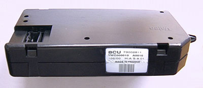
 SM023 - VALEO BCU (DISCO II) - Diagnostic Capabilities (Read Fault Codes)