WABCO D TYPE (DEFENDER) - System Overview
The first and only fitment of ABS to a Defender and was introduced in 1999.
SM033 - WABCO D TYPE (DEFENDER) - System Help file
Version 1.27

WABCO D TYPE (DEFENDER) - Known Fitments
Vehicle makes, models and variants known or believed to be using this vehicle system, required diagnostic lead and degree of known compatibility.

Vehicle Make Vehicle Model Vehicle Variant Diagnostic Lead
Land Rover Defender 1998> Black OBDII Lead

WABCO D TYPE (DEFENDER) - Physical Details

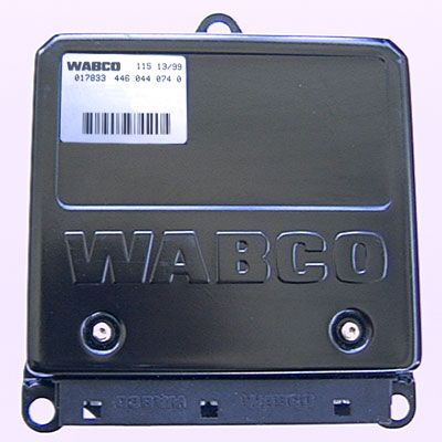
WABCO D TYPE (DEFENDER) - Pin Outs
Details of the pin usage for the ECU connector(s).

Connector 1
1 Front LH Wheel Sensor
2 Front LH Wheel Sensor
3 Rear RH Wheel Sensor
4 Front RH Wheel Sensor
5 Front RH Wheel Sensor
6 Rear RH Wheel Sensor
7 Rear LH Wheel Sensor
8 Rear LH Wheel Sensor
9 Not Used

Connector 2
1 Battery
2 Ignition
3 Road Speed Output
4 Not Used
5 Diagnostic
6 Not Used
7 Reverse Gear
8 Return Pump Monitor
9 Not Used
10 Throttle Position Sensor
11 1st Gear
12 Earth
13 ETC Information Lamp
14 Hill Descent Active
15 Not Used
16 HDC Fault
17 HDC Information Lamp
18 ABS Warning Lamp

Connector 3
1 Solenoid Valves Front Left
2 Solenoid Valves Front Left
3 Reference Ground
4 Solenoid Valves Front Right
5 Solenoid Valves Front Right
6 Shuttle Valve Switch
7 Solenoid Valves Rear Left
8 Solenoid Valves Rear Left
9 Not Used
10 Solenoid Valves Rear Right
11 Solenoid Valves Rear Right
12 ABS Relay
13 - 14 Not Used
15 ABS Return Pump Relay

SM033 - WABCO D TYPE (DEFENDER) - Diagnostic Capabilities (Read Fault Codes)
Reads the fault code memory. The ECU can self detect up to 47 different problems with itself, its wiring and its associated sensors, storing the respective code if it detects any malfunction or reading outside of pre defined acceptable limits. Not all stored faults may cause the fault warning lamp to illuminate.

SM033 - WABCO D TYPE (DEFENDER) - Diagnostic Capabilities (Clear Fault Codes)
This function first reads the fault code memory to ensure that there are faults to clear and if there are completely erases and clears the fault code memory. Having deleted the faults it then re-checks the fault memory to check that it is clear, reporting success if it is. Failure to clear the fault memory successfully is usually due to the system re-logging the fault the moment the fault memory is clear. This indicates that the fault has not been rectified properly and as far as the system is concerned still exists. A re-check for successful clearing of the fault code memory may be successful but then the system may re-log the fault shortly after.

SM033 - WABCO D TYPE (DEFENDER) - Diagnostic Capabilities (Settings)
Values, configuration settings, and other stored information which can be read from the ECU, edited and then rewritten back. Read settings can also be stored as a standard HTML page for reference. These pages can then later be re loaded and re written back to the ECU. Please note that some values may be read only due to the fact that they are supplied from the ECU’s ROM or are internally calculated.<

  • Product number: This is a Wabco assigned number which tells them which variation of the same family this ECU is.
  • Product date: This code is used to identify how far into production of this particular variant of this ECU type it was when this individual ECU was built. This would help if a build error was detected and a recall was required.
  • Bar code: This is the bar code by which stocks of this ECU can be electronically controlled. The bar code itself and the number it represents can also be found on the outer case of the ECU.
  • Factory code: This is a Wabco number by which they can identify the production line which built this ECU.
  • ABS module: The ABS ECU is a multi function ECU which can manage the functions of Anti-lock Braking (ABS), Electronic Brake Distribution (EBD), Electronic Traction Control (ETC) and Hill Descent Control (HDC). These different functions all share the same measurements taken from the connected sensors and often control the same valves in conjunction with one another. They also communicate diagnostically as one unit through the same shared connection. This means that each function is treated as a separate module within the ECU and it is possible for any module to be modified independently of the others. For this reason each module has its own reference code by which changes can be traced if required. This is the code for the ABS module.
  • Diagnostic module: This is the code for the Diagnostic module if fitted (see ABS module for details).
  • Measurement module: This is the code for the Measurement module if fitted (see ABS module for details).
  • Traction control: This is the code for the ETC module if fitted (see ABS module for details).
  • EBD module: This is the code for the EBD module if fitted (see ABS module for details).
  • HDC module: This is the code for the HDC module if fitted (see ABS module for details).
  • VIN: This is the vehicle's unique VIN number.

SM033 - WABCO D TYPE (DEFENDER) - Diagnostic Capabilities (Inputs)
Realtime live display of the information the electronic control unit of the selected vehicle system is currently deriving from its input sensors.

  • Wheel speed sensor voltage: This shows the DC Voltage for the right front wheel speed sensor. Expected values are between 2.0 to 2.4 Volts.
    The wheel speed sensors are different to the conventional wheel speed sensors used on other Land Rover products. Conventionally, wheel speed sensors have an interference fit with the hub or back plate. This positions the sensor close to a reluctor ring. The sensors used are incorporated into the inboard wheel bearing, on both front and rear hubs. This bearing assembly is a sealed unit and has no replaceable parts. Also different is the wire from the wheel speed sensor. Land Rover has, historically used a wheel speed sensor employing a signal wire inside a shielded earth wire. The new wheel speed sensors have a twisted pair of wires. This offers some electrical advantages over two straight wires. Such as the signal being less susceptible to electrical noise or interference and it generates less electrical noise, the wires can also be balanced together (similar electrical properties) to ensure voltage losses are minimized. Like a conventional wheel speed sensor, the signal created is an AC sine wave. This wave is generated in the inductive sensor by a sixty-tooth reluctor, machined into the wheel bearing inner race. The frequency of this signal supplies the ABS ECU with the information it needs to determine the speed of the individual wheels and is used in the calculation of vehicle speed or vehicle reference speed.
  • Outlet valve: This shows the voltage being applied to this valve by the ABS ECU. When driven the voltage should be around 2.8 to 3.6 Volts and when not being driven should be around 0 to 0.5 Volts.
  • Inlet valve: This shows the voltage being applied to this valve by the ABS ECU. When driven the voltage should be around 2.8 to 3.6 Volts and when not being driven should be around 0 to 0.5 Volts.
  • Wheel speed: The wheel speed in KPH. The ABS ECU cannot detect wheel speeds less than 1.8 KPH. The wheel speed sensors are different to the conventional wheel speed sensors used on other Land Rover products. Conventionally, wheel speed sensors have an interference fit with the hub or back plate. This positions the sensor close to a reluctor ring. The sensors used are incorporated into the inboard wheel bearing, on both front and rear hubs. This bearing assembly is a sealed unit and has no replaceable parts. Also different is the wire from the wheel speed sensor. Land Rover has, historically used a wheel speed sensor employing a signal wire inside a shielded earth wire. The new wheel speed sensors have a twisted pair of wires. This offers some electrical advantages over two straight wires. Such as the signal being less susceptible to electrical noise or interference and it generates less electrical noise, the wires can also be balanced together (similar electrical properties) to ensure voltage losses are minimized. Like a conventional wheel speed sensor, the signal created is an AC sine wave. This wave is generated in the inductive sensor by a sixty-tooth reluctor, machined into the wheel bearing inner race. The frequency of this signal supplies the ABS ECU with the information it needs to determine the speed of the individual wheels and is used in the calculation of vehicle speed or vehicle reference speed.
  • Brake switch 1: This shows the status of the brake switch no 1.
  • Brake switch 2: This shows the status of the brake switch no 2.
  • Pressure switch 1: This shows the status of the pressure switch no 1.
  • Pressure switch 2: This shows the state of the pressure switch no 2.

SM033 - WABCO D TYPE (DEFENDER) - Diagnostic Capabilities (Outputs)
Choice of outputs that can be tested. Each output has an ON and OFF choice. Click on the ON link to start the test and on OFF to end.

  • Valves: This turns on the output to the ABS valves (front/rear left/right inlet/outlet).
  • Pump relay: This turns on and off the ABS pump relay output.
  • Valve relay: This turns on and off the ABS valve relay output.
  • Brake warning LED: This turns on the brake warning lamp for 20 seconds. The brake or EBD lamp is a combined warning lamp with the low brake fluid warning and the handbrake warning lamp. The lamp is a red light with an exclamation mark inside a brake symbol. The ABS ECU will illuminate this light if it senses a fault that will affect its ability to control the braking balance of the vehicle. This lamp will be illuminated for 3 seconds when the ignition is switched on, as a bulb check function. It will then extinguish as long as no fault currently exists that may effect the operation of the EBD. The EBD warning lamp will remain illuminated if the ABS ECU is in "new-born" mode. Unlike the ABS warning lamp, the ABS ECU supplies a voltage to illuminate the light, not to turn it off. Modes of operation:
    • No lamp and no audible warning indicate that the ABS/EBD/TC and HDC systems are OK.
    • The lamp being on could indicate that the ignition has just been turned on (Bulb check for 3 seconds), the handbrake is on, there is a low brake fluid level, the ABS ECU supplied voltage is much too high or much too low‚ there is a new-born ABS ECU fitted, the ABS has a sensor/pump or valve fault logged for this journey.
    • Both lamp on and the audible warning indicates that the ABS has detected a sensor/pump or valve fault.
  • ABS warning LED: The ABS warning lamp is an amber light with the letters ABS inside a circle. If there is a fault the ABS warning lamp will remain illuminated until the ignition is switched off.
  • Traction control lamp: The ETC system employs one amber lamp, which has the letters TC in a dotted circle. The lamp will illuminate during the ignition on lamp check. The system will indicate TC operation by illuminating the amber TC lamp for a minimum of 2 seconds.
  • Speedometer: This drives the speedometer output to simulate 100 Miles per hour.
  • HDC information LED: This lamp is used by the HDC system to indicate that the system is switched on and ready to assist with descents, when necessary.
  • HDC fault LED: This turns on the output for the HDC fault lamp/LED. The HDC amber lamp is used to indicate a fault with the system. The graphic is the same as the green HDC light, but has an additional exclamation mark next to it. The moment a fault appears that will affect the operation of the HDC function, an audible warning is sounded, similar to the ABS fault warning, and the amber light will be illuminated.

SM033 - WABCO D TYPE (DEFENDER) - Diagnostic Capabilities (Other)
Choice of functions that can be performed.

  • ABS power bleed: This causes the ABS system to bleed the main hydraulic circuit and may need to be repeated if there is a substantial amount of air in the circuit.
  • ABS modulator bleed: This causes the ABS system to bleed the secondary hydraulic circuit and may need to be repeated if there is a substantial amount of air in the circuit.