Values, configuration settings, and other stored information which can be read from the ECU, edited and then rewritten back. Read settings can also be stored as a standard HTML page for reference. These pages can then later be re loaded and re written back to the ECU. Please note that some values may be read only due to the fact that they are supplied from the ECU’s ROM or are internally calculated.
Clicking on the settings link, it will open a page with two choices, "Settings and Information" and "Coding Data". The first page contains information about Lucas 5 AS alarm, settings information, and gives the possibility to change different settings of the alarm. The second page contains only coding data, and is to be used only to program a new ECU.
GENERAL SETTINGS
- MEMS code: This is the code transmitted by the 5AS alarm unit. It can have any value between 0 and 65535.
- Bad plip keycode allowance: This is the number of invalid plip codes the alarm will accept before triggering.
- Number of plip learnt: This is the number of plips learnt by the 5AS alarm.
- Plip keycode: The plip code information uniquely identifies each key it is split in 4 parts. It is possible to obtain the number for any given key by learning it to the 5AS alarm and then reading this number from the alarms memory. Once you know what the number is for any given plip you can then simply type in its code into any alarm you wish to react to it.
- Plip presses for easy synchronization: This is the number of presses of the plip to allow an easy resynchronization.
- Plip presses for resynchronization: During a resynchronization of the plips, the plip has to be pressed this number of times.
- Plip presses for low battery: To rule out spurious errors the alarm must receive more than one consecutive transmission of a plip in which the low battery indication is set. This value is the number of successive transmissions to be received before the alarm activates the low battery indication via the security LED.
- EKA code: This is a special Emergency Key Access code which can be entered into the alarm using either the door lock or in the door ajar switch. Exact details of the procedure can be found in the vehicles handbook.
- Alarm serial number: This is the serial number of the alarm as printed on a label affixed to the lid.
- Week of build: This is the week of the year when the ECU was manufactured.
- Year of build: This is the year the ECU was manufactured.
- Alarm sound: This setting determines if the horn will sound in a continuous tone or if it will be pulsed when the alarm has been triggered.
- Time Synchronize: Both the alarm and the plip each have a timer in them which stays in synchronization and can be used as part of the correct key verification sequence every time the key is used. Setting this value to No turns off this function.
- Time Error: Both the alarm and the plip each have a timer in them which stays in synchronization and can be used as part of the correct key verification sequence every time the key is used. However it is possible for one of the timers to run marginally faster or slower than the other. Setting this value to yes allows the alarm to accept an error rate of up to 9 seconds in every hour between the two as a pass.
- Resync on lock: When set to ENABLED the alarm and the key will synchronize to each other whenever the vehicle is locked.
- Resync on arm: When set to ENABLED the alarm and the key will synchronize to each other whenever the alarm is armed.
- Low Battery: When set to ENABLED this configures the alarm to notify the user via the security LED that the plip has a low battery in accordance with the other settings which affect this function's operation. When set to NO the function is totally disabled.
- Low battery error: This configures the alarm to notify the user via the Security LED either on the first receipt of a key code in which the low battery flag is set or to wait until it has received a number of them in succession. The exact number is determined by the value stored in the LOW BAT COUNT box.
CODING DATA
- Coding Data 1-32: 32 blocks of programmable data stored in the ECU to control its functionality for specific variations of vehicle. There are a number of hexadecimal digits, each digit separated by a comma. Re-entered parameters should be entered in an identical format to that which is read. Changing this values can produce unknown alteration in the functionality of the ECU, damage the ECU or even damage your car.
|
 LUCAS 5AS ALARM - System Overview
 LUCAS 5AS ALARM - Known Fitments
 LUCAS 5AS ALARM - Physical Details
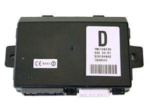
 SM034 - LUCAS 5AS ALARM - Diagnostic Capabilities (Read Fault Codes)