BOSCH DDE4 TD4 - System Overview
Quite a sophisticated Diesel Engine management system ECU. Manufactured by Bosch, this ECU is most often referred to in BMW terminology as version 4.0 of its DDE (Digital Diesel Electronics) series. However in Bosch terminology circles the physical ECU itself can often be denoted having some sub suffix of the EDC (Electronic Diesel Control). Being a flash based ECU with a huge memory the entire code that controls its operationally and functionality including its self diagnostic capability is determined by whatever version of software is programmed into it. This means that although the ECU may be physically the same as that used in other applications such as the TD6 Range Rover, dramatic changes in the communications and the coding mean that different applications require different modules. This module is specifically written deals with the ECU when programmed to suit the small four cylindered Turbo dies engine found in the TD4 Freelander introduced for 2001 onwards up to present day and a small variety of similarly aged Rover and MG vehicles.

Although it is a modern enough ECU to fully support the limited degree of information and fault codes provided for by enforced OBDII compliance, there are of course many more fault codes, functions and features that this module gives access to including security link learning and re synchronization.
SM036 - BOSCH DDE4 TD4 - System Help file
Version 1.22

BOSCH DDE4 TD4 - Known Fitments
Vehicle makes, models and variants known or believed to be using this vehicle system, required diagnostic lead and degree of known compatibility.

Vehicle Make Vehicle Model Vehicle Variant Diagnostic Lead
Land Rover Freelander 2001-2005 Black OBDII Lead
Rover 75 All diesels Black OBDII Lead
Rover 75 Tourer All diesels Black OBDII Lead
MG - Rover ZT All diesels Black OBDII Lead
MG - Rover ZT-T All diesels Black OBDII Lead

BOSCH DDE4 TD4 - Physical Details


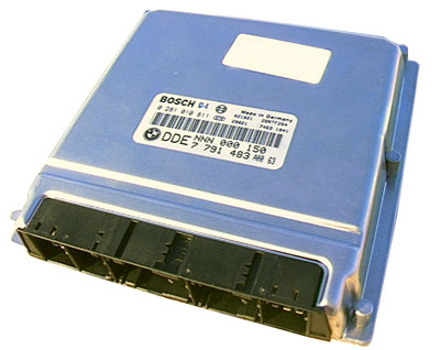
BOSCH EDC TD4 - Pin Outs
Details of the pin usage for the ECU connector(s).

C0331
1 Charge Check Alternator
2 Not Used
3 Not Used
4 Engine Fan Control
5 Not Used
6 Not Used
7 APP Sensor Earth
8 APP Sensor signal
9 APP Sensor supply
10 Fuel Pump
11 Oil Pressure Sensor
12 APP Sensor Earth
13 APP Sensor signal
14 APP Sensor supply
15 Not Used
16 Not Used
17 Not Used
18 Not Used
19 Not Used
20 Not Used
21 Not Used
22 Vehicle Speed switch
23 Clutch switch
24 Brake switch main circuit
25 Not Used
26 Ignition Voltage
27 Cruise Control ECU MFL signal
28 Brake switch test circuit
29 Compressor relay
30 Not Used
31 Not Used
32 Diagnostic interface
33 Immobilisation
34 Not Used
35 Not Used
36 CAN bus high
37 CAN bus low
38 Not Used
39 Not Used
40 Not Used

C0332
1 Supply electronic fuel injector cylinders 2 and 4
2 Not used
3 Electronic fuel injector cylinder 2
4 Supply electronic fuel injector cylinders 1 and 3
5 Electronic fuel injector cylinder 1
6 Electronic fuel injector cylinder 4
7 Not used
8 Electronic fuel injector cylinder 3
9 Not used

C0603
1 Battery voltage input
2 K line diagnostic interface
3 Not used
4 Earth
5 Earth
6 Earth
7 Ignition voltage
8 Main relay supply
9 Main relay earth

C0604
1 Not used
2 Not used
3 Not used
4 Not used
5 Not used
6 Not used
7 Not used
8 Not used
9 Fuel pressure sensor supply
10 Fuel pressure sensor earth
11 Not used
12 Not used
13 Not used
14 Not used
15 Not used
16 Not used
17 Fuel pressure sensor signal
18 Not used
19 Not used
20 Not used
21 Not used
22 Not used
23 Not used
24 Not used
C0606
1 MAF sensor supply
2 MAF sensor signal
3 MAF sensor earth
4 CMP signal
5 Not used
6 CKP signal
7 Not used
8 Not used
9 Fuel pressure sensor supply
10 EGR
11 Not used
12 Glow plug control
13 Not used
14 Boost pressure sensor supply
15 Boost pressure sensor signal
16 Boost pressure sensor earth
17 CMP earth
18 Not used
19 Speed signal screen earth
20 Fuel rail pressure sensor earth
21 Not used
22 Not used
23 Boost control solenoid valve supply
24 Not used
25 Not used
26 Not used
27 Not used
28 ECT signal
29 IAT signal
30 Not used
31 CKP earth
32 ECT Earth
33 Fuel rail pressure sensor signal
34 Not Used
35 Fuel rail pressure sensor supply
36 Not used
37 Not used
38 Fuel Pressure regulator
39 Not used
40 Not used
41 Oil pressure switch
42 Not used
43 Not used
44 Not used
45 Not used
46 Not used
47 Not used
48 Not used
49 Not used
50 Charge Check alternator
51 Not used
52 Fault status glow plug relay

SM036 - BOSCH DDE4 TD4 - Diagnostic Capabilities (Read Fault Codes)
Reads the fault code memory. The ECU can self detect up to 25 different categories of problem with itself, its wiring and its associated sensors, storing the respective code if it detects any malfunction or reading outside of pre defined acceptable limits. Not all stored faults may cause the fault warning lamp to illuminate.

SM036 - BOSCH DDE4 TD4 - Diagnostic Capabilities (Clear Fault Codes)
Clears the fault code memory.

SM036 - BOSCH DDE4 TD4 - Diagnostic Capabilities (Settings)
Values, configuration settings, and other stored information which can be read from the ECU, edited and then rewritten back. Read settings can also be stored as a standard HTML page for reference. These pages can then later be re loaded and re written back to the ECU. Please note that some values may be read only due to the fact that they are supplied from the ECU’s ROM or are internally calculated.

SETTINGS INFORMATION
  • Week of build: This shows the manufacturing week of the ECU.
  • Year of build: This shows the manufacturing year of the ECU.
  • Part number: This is the manufacturer's part number for the ECU.
  • Idle Speed: This is the idle speed of the engine.
HISTORY RECORDS 1-12: There are 12 history records storing information related to the programming of the ECU.
  • VIN number: Vehicle's identification number.
  • Programming date: The date the ECU was programmed.
  • Assembly number: This is a unique number which defines the ECU hardware and software combination.

SM036 - BOSCH DDE4 TD4 - Diagnostic Capabilities (Inputs)
Realtime live display of the information the electronic control unit of the selected vehicle system is currently deriving from its input sensors.

GENERAL
  • Manifold pressure (KPa): This shows the pressure measured by the pressure sensor mounted in the air intake manifold. Normal values with engine idle between 80 - 125 KPa. The value can reach 260 KPa when the engine speed reaches high valued (around 3000 rpm).
  • Fuel pressure regulator: This shows the current drawn by the fuel pressure regulator valve on the low pressure side of the system. This value is around 1 amp when engine idle.
  • Air flow Mg/fire: This shows measured mass airflow. This reading shows the amount of air which is being used by the EGR control. As EGR increases, the airflow reduces.
  • Inlet air temp: This shows the current temperature of the air at the engine air intake. The measurement is taken using the intake air temperature sensor. This value is used by the ECU to adjust the ignition timing. A poor operation of the intake air temperature sensor can produce errors in adjusting the EGR.
  • Pedal demand 1 (V): This shows the output voltage of the driver demand potentiometer 1 as read by the ECU. Normal values are around 0.7V with the pedal released and 4V when the pedal is fully depressed.
  • Pedal demand 2 (V): This shows the output voltage of the driver demand potentiometer 2 as read by the ECU. Normal values are around 0.4V when the pedal is released and 2V when the pedal is fully depressed.
  • Coolant temperature: This shows the current temperature as read by the engine coolant temperature sensor. The meter bands show the expected value range on a fully warm engine. A faulty sensor can cause poor starting; the cooling fan will run permanently, abnormal fuel consumption.
  • Engine speed: This shows the engine speed in revolutions per minute as received from the crank sensor signal.
  • Rough cly 1: This shows the fluctuations in cylinder 1 speed in rpm. Under normal operating conditions this is compensated for by the cylinder balancing routine.
  • Rough cly 2: This shows the fluctuations in cylinder 2 speed in rpm. Under normal operating conditions this is compensated for by the cylinder balancing routine.
  • Rough cly 3: This shows the fluctuations in cylinder 3 speed in rpm. Under normal operating conditions this is compensated for by the cylinder balancing routine.
  • Rough cly 4: This shows the fluctuations in cylinder 4 speed in rpm. Under normal operating conditions this is compensated for by the cylinder balancing routine.
  • High pressure rail (KPa): This shows the fuel pressure measured by the ECU on the high pressure side of the system using the fuel rail pressure sensor. Normal values at idle speed are around 30000KPa and while cranking 20500KPa. A value of 15000KPa denotes that the sensor is open circuit.
  • Battery voltage: This is the voltage of the battery.
  • Sensor supply 1(V): This displays the regulated supply voltage for the sensor supplies and pedal demand potentiometers.
  • Sensor supply 2 (V): This displays the regulated supply voltage for the sensor supplies and pedal demand potentiometers.
  • Low pressure supply (KPa): This shows the fuel pressure measured by the ECU on the low pressure side of the system. The value is read from the fuel supply pressure sensor fitted in the top of the fuel filter. Normal values are around 420KPa when idle and 120KPa while cranking.
  • Brake test switch: This shows the state of the footbrake pedal brake switch 1 as seen by the ECU.
  • Brake light switch: This shows the state of the footbrake pedal brake switch 2 as seen by the ECU.
  • Clutch switch: This shows the position of the clutch pedal as determined by the clutch switch. When the switch fails, a decrease in drivability can be noticed.
CYLINDER BALANCING
  • Cylinder 1(mm³): This shows the adjustment in fuelling for cylinder 1 so that each cylinder is running at the same speed.
  • Cylinder 2(mm³): This shows the adjustment in fuelling for cylinder 2 so that each cylinder is running at the same speed.
  • Cylinder 3(mm³): This shows the adjustment in fuelling for cylinder 3 so that each cylinder is running at the same speed.
  • Cylinder 4(mm³): This shows the adjustment in fuelling for cylinder 4 so that each cylinder is running at the same speed.

SM036 - BOSCH DDE4 TD4 - Diagnostic Capabilities (Outputs)
Choice of outputs that can be tested. Each output has an ON and OFF choice. Click on the ON link to start the test and on OFF to end.

  • Glow plug: The glow plug can be turned on or off.
  • Cooling fan: The fan can be set to one of the speeds: slow, medium speed, fast or off. Note that the fan will not start from slow, has to be turned of fast first.
  • EGR: The EGR can be turned on and off when fitted.
  • Air condition compressor: The AC compressor can be turned on or off.

SM036 - BOSCH DDE4 TD4 - Diagnostic Capabilities (Other)
Function that can be performed.

  • Start Synchronization with immobiliser ECU: This causes the engine management ECU to go into Learn Mode where it will learn the next output from the immobiliser ECU and synchronize with it.
    The synchronization procedure is done in three steps that should take place in one ignition cycling.
    1. Put the engine management in learning mode: This function is to be found in the engine management START SYNCHRONIZATION WITH IMMOBILISER ECU. The function will set the ECU into learning mode. Once you've been prompted that the engine management is in learning mode, navigate in the Vehicle Explorer to the immobiliser for step 2.
    2. Send code from immobiliser ECU: This function is to be found in the immobiliser SYNCRONIZE WITH ENGINE MANAGEMENT SYSTEM. This function will send codes to be learned. Once you've been prompted that the immobiliser sent the code successfully, navigate in the Vehicle Explorer to the engine management for step 3.
    3. Take the engine management out of learning mode: This function is to be found in the engine management END SYNCHRONIZATION WITH IMMOBILISER ECU. The function will end the learning mode, leaving the ECU in normal mode.
  • End Synchronization with immobiliser ECU: This causes the engine management ECU to acknowledge the code sent by the immobiliser ECU and to exit Learn Mode.
  • Read security status: This function reads the security status of the ECU.