SM037 - SIEMENS EMS 2000 - System Help file
Version 1.22

SIEMENS EMS 2000 - Known Fitments
Vehicle makes, models and variants known or believed to be using this vehicle system, required diagnostic lead and degree of known compatibility.

Vehicle Make Vehicle Model Vehicle Variant Diagnostic Lead
Land Rover Freelander V6 Excluding NAS Black OBDII Lead
Rover 75 V6 Black OBDII Lead
MG MGZT V6 Black OBDII Lead
Rover 45 V6 Black OBDII Lead
Rover 75 V6 Black OBDII Lead
MG ZS V6 Black OBDII Lead
MG ZT V6 Black OBDII Lead
MG ZT-T V6 Black OBDII Lead

SIEMENS EMS 2000 - Physical Details

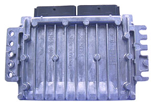
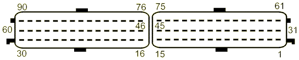
SIEMENS EMS 2000 - Pin Outs
Details of the pin usage for the ECU connector(s).

 
1 Ignition Coil 4
2 Ignition Coil 3
3 Header Earth
4 Purge Control Valve
5 - 6 Not Used
7 Main Relay Control
8 Valve Balance
9 Fuel Pump Relay Control
10 Interface Cruise Control
11 Not Used
12 Sensor Inlet Air Temperature
13 Sensor Heated Oxygen
14 Sensor Heated Oxygen (Front)
15 Sensor Coolant Temperature Gauge
16 Oxygen Sensor VLS
17 Switch Dual Pressure
18 Sensor Crankshaft Position
19 Sensor Camshaft Position
20 Sensor Knock
21 Vehicle Speed
22 Not Used
23 Valve butterfly
24 - 26 Not Used
27 CAN
28 Header Earth
29 Ignition In
30 Not Used
31 Ignition Coil 6
32 Ignition Coil 5
33 Header Earth
34 Sensor Heated Oxygen (Front)
35 Oxygen Sensor LSH
36 Sensor Heated Oxygen
37 Not Use
38 Valve Butterfly
39 - 41 Not Use
42 Idle Air Control Valve
43 Not Used
44 Sensor Throttle Position (Earth)
45 Sensor Coolant Temperature Gauge
46 Evap Temp
47 Sensor Inlet Air Temperature
48 Not Used
49 Switch Throttle Pedal
50 Sensor Knock
51 Alternator
52 Immobilisation
53 Switch Dual Pressure
54 Sensor Crank Shaft Position
55 Not Used
56 K-Line
57 CAN
58 Fuel Injector Number 4
59 Fuel Injector Number 2
60 Fuel Injector Number 1
61 Ignition Coil 1
62 Ignition Coil 2
63 Header Earth
64 Mag Clutch
65 Not Used
66 Main Supply In
67 Header Earth
68 Not Used
69 Control Unit Cooling Fan
70 Idle Air Control Valve
71 Idle Air Control Valve
72 Idle Air Control Valve
73 Sensor Inlet Air Temperature
74 Sensor Throttle Position
75 Sensor Throttle Position
76 Oxygen Centre Earth
77 Oxygen Sensor -ve
78 Sensor Inlet Air Temperature
79 Not Used
80 Sensor Knock
81 Switch Dual Pressure
82 Sensor Camshaft Position
83 Not Used
84 Valve Balance
85 Vacuum Enhance
86 - 87 Not Used
88 Fuel Injector Number 3
89 Fuel Injector Number 5
90 Fuel Injector Number 6

SM037 - SIEMENS EMS 2000 - Diagnostic Capabilities (Read Fault Codes)
Reads the fault code memory. The ECU can self detect up to 105 different problems with itself, its wiring and its associated sensors, storing the respective code if it detects any malfunction or reading outside of pre defined acceptable limits. Not all stored faults may cause the fault warning lamp to illuminate.

SM037 - SIEMENS EMS 2000 - Diagnostic Capabilities (Clear Fault Codes)
This function clears the fault code memory. Failure to clear the fault memory successfully is usually due to the system relogging the fault the moment the fault memory is clear. This indicates that the fault has not been rectified properly and as far as the system is concerned, still exists. The recheck for successful clearing of the fault code memory may be successfully executed but then the system may relog the fault shortly after.

SM037 - SIEMENS EMS 2000 - Diagnostic Capabilities (Settings)
Values, configuration settings, and other stored information which can be read from the ECU, edited and then rewritten back. Read settings can also be stored as a standard HTML page for reference. These pages can then later be reloaded and rewritten back to the ECU. Please note that some values may be read only due to the fact that they are supplied from the ECU's ROM or are internally calculated.

  • GM Code: This is a unique code that identifies the configuration of the vehicle. It is stored in several ECUs within the vehicle and allows the manufacturer to uniquely identify each and every possible option for the vehicle. It is used in conjunction with the SA Code and the VN Code. The function to decode these into their meanings and to create a code from options is in the "Other Systems" section under the main menu of Freelander. The code is formatted by 8 hex numbers.
  • SA Code: This is a unique code that identifies the configuration of the vehicle. It is stored in several ECUs within the vehicle and allows the manufacturer to uniquely identify each and every possible option for the vehicle. It is used in conjunction with the GM Code and the VN Code. The function to decode these into their meanings and to create a code from options is in the "Other Systems" section under the main menu of Freelander. The code is formatted by 8 hex numbers.
  • VN Code: This is a unique code that identifies the configuration of the vehicle. It is stored in several ECUs within the vehicle and allows the manufacturer to uniquely identify each and every possible option for the vehicle. It is used in conjunction with the SA Code and the GM Code. The function to decode these into their meanings and to create a code from options is in the "Other Systems" section under the main menu of Freelander. The code is formatted by 5 hex numbers.
  • VIN Number: This is the vehicle identification number.
  • Programming date: This is the date in day/month/year that the Engine Management was last programmed.
  • Assembly number: This is a unique number which defines the ECU hardware and software combination.
  • Homologation number: This is the recorded emission control test number (Homologation) which is allocated to the ECU configuration / fuel tune map set by the respective authority.
  • Programming station: This is the code of the station where the ECU was programmed.
  • Mileage at programing date: The mileage at the time of programming.
  • AIF status: The status of the AIF field.
  • Part Number: This is the Siemens part number for this ECU.
  • Calibration number:
  • Hardware number: This is the hardware version which denotes the processor and circuit board type.
  • Siemens software number: This denotes the coding inside the processor for the hardware.
  • Hardware version number:
  • Coding Index: The coding index for this ECU.
  • Diagnostic Index: The diagnostic index for this ECU.
  • Bus Index: The bus index for this ECU.
  • Manufacturing date: This is the date the ECU was manufactured.
  • Supplier code:
  • ECU software version number:
PROGRAMMING RECORDS (Flash type ECUs only)
The ECU has an area of memory allocated for programming history records. Each record, which is a fixed length contains the VIN number, programming date, assembly number, Homologation number and some unused hexadecimal data. Whenever a new record is added, it is placed after the last record and then becomes the active record which diagnostic equipment such as TestBook reads to obtain information about what an ECU is currently programmed with to see if there are any updates required to be programmed into it. It also uses the absence of any records to indicate a new ECU, which is the only time it allows a vehicle configuration change as from then on it uses the last Assembly number to dictate the maps uses to update the ECU with. It does not appear to verify that the actual maps in the ECU are those indicated by the Assembly number shown in the last / Active programming record, or read previous records. It is not diagnostically possible to erase or modify existing programming records. The space calculates to a possible total of 178 records, however, given that other ECU's such as the Motronic 5.2.1 are limited to only 14 records before the ECU can no longer be updated and must be replaced, which ultimately results in additional ECU sales. It is therefore likely that the ECU may well not accept the programming of all 178 possible spaces.

The page shows a space for a New Record Entry, to be filled in for programming, the Active Record, which is the actually the last record, is then shown under that and is provided here as a duplicate of the last record simply to save having to scroll to the bottom of a possibly long list to get to the last record and the used Programming Records from 1 to the last one used. This page also gives access to the map database by clicking on "MAP DATABASE" button at the bottom of the page.
  • VIN number: This is the vehicle's VIN number and it can be programmed only when an ECU is reprogrammed by a Test Book.
  • Programming date: This is the date the ECU was programmed.
  • Assembly number: This is the Assembly number.
  • Homolog. number: This is the recorded emission control test number (Homologation) which is allocated to the ECU configuration / fuel tune map set by the respective authority.
  • Programming station: This is the station used to program the ECU.
  • Odometer value: This is the odometer value at the programming time.
  • Unused data: Data that currently has no known usage but as something is required to be supplied when programming a new record, it has to be filled in. We suggest that you use the same data taken from the last programming record, which can be typed in manually or cut and pasted in using CTRL-C and CTRL-V key combinations.
  • Database Data: By clicking on this link, it will open a special database that allows you to see and browse all the known Assembly numbers and their respective information about them. The Database will open with the record highlighted for the Assembly number from the active / last programming record For more information on how to use this map database, see Map Database.

SM037 - SIEMENS EMS 2000 - Diagnostic Capabilities (Inputs)
Realtime live display of the information the electronic control unit of the selected vehicle system is currently deriving from its input sensors.

GENERAL PAGE 1
  • Road speed (km/h): This is the vehicle's speed measure in km/h. The speed signal measured by ABS ECU is passed over the CAN bus via the automatic transmission ECU to the Siemens 2000 ECU.
  • Engine RPM: This is the engine speed in revolutions per minute, measured using the crankshaft sensor.
  • Manifold pressure: This shows the absolute throttle plate pressure in kilopascals.This bias measured using the air temperature MAP sensor. The manifold pressure value will vary widely when engine is running and different loads are applied. (air conditioning, steering, etc.).
  • Purge Valve Duty (%): This shows the current duty cycle ratio of the canister purge valve as a percentage. 99 % represents fully open and 0% closed. The valve will not open until the coolant temperature is above 75 °C and the engine speed above 1600 RPM.
  • Mass Air Flow (mg/stk): This shows the air flow through the manifold after the throttle flap in milligrams per stroke. Mass airflow is an indication of engine load and can be used as an indicator of air leaks in the manifold.
  • Crankshaft Signal: This shows whether the crankshaft sensor is functioning correctly. An error with this sensor means that the engine will not be able to synchronize and it will not be possible to start the engine.
  • Camshaft Signal: This shows the status of the camshaft signal. The status is Detected and Error. The Error status is set when is no signal detected or the signal is detected when it shouldn't have.
  • Cruise Control: This shows if the input to the cruise control interface unit from the engine management ECU has been enabled.This output will be enabled if the gear selector is in DRIVE, ignition is ON and cruise master switch is ON.
  • Fuel Pump Relay: This shows if the fuel pump relay is on or off.
  • Throttle Pedal Status: This shows the throttle pedal status. This parameter is sent from the Siemens 2000 ECU via the CAN bus to the ABS ECU indication whether throttle pedal is pressed or not. The parameter is used by the HDC for safety monitoring.
  • Throttle Switch Fault Status: This shows the throttle switch fault status. The parameter is sent from Siemens 2000 ECU via the CAN bus to the ABS ECU indicating whether the throttle switch has a current fault present. This is used by the HDC for safety monitoring.
  • Throttle Switch Input: This shows the throttle switch input directly into the Siemens 2000 ECU.
  • HDC Status: This shows the hill descent control state. The parameter indicating the current state of the HDC is send from the ABS ECU to the Siemens 2000 ECU. HDC is controlled by ABS ECU.
  • A/C Switch: This display the status of the air condition switch.
  • A/C Clutch Drive: This shows the status of the air condition clutch drive. When the air condition drive is ON, the A/C compressor clutch should operate when required. The granting for the enable signal is dependent on temperature, engine speed and throttle position and as such the A/C clutch drive may not change immediately.
  • A/C Relay: This shows the status of the air condition compressor relay. When the relay is on, the compressor clutch should operate, dependent on evaporative temperature pressure.
  • Cooling Fan Duty Cycle (%): This shows the duty cycle of the cooling fan. The values should be between 10 - 90, depending on the temperature of the coolant and whether the air conditioning is in use.
  • Variable Intake Balance Valve: This shows the status of the variable intake balance valve. This valve is used to control the flow of mixture into the intake manifold. The valve is open when deactivated and closed when activated.
  • Variable Intake Butterfly Valve: This shows the status of the six variable intake butterfly valves. These valves are used to control the flow of volume into the intake manifold. The valves are open when deactivated and closed when activated.
  • Variable Intake Balance Valve Feedback: This shows the current position of the variable intake balance valve. This display shows feedback, which confirms when the balance valve has reached its closed position.
  • Variable Intake Butterfly Valve Feedback: This shows the current position of the six variable intake butterfly valves. This display shows feedback, which confirms when all six butterfly valves have reached their closed position.
  • Odd Bank Rich: This shows whether rich mixture has been detected on the odd cylinder bank.
  • Even Bank Rich: This shows whether rich mixture has been detected on the odd cylinder bank.
  • Odd Bank Closed Loop Status: This shows whether closed loop control is enabled on the odd cylinder bank.
  • Even Bank Closed Loop Status: This shows whether closed loop control is enabled on the odd cylinder bank.
  • Engine Running: This displays the engine running status.
  • Engine Synchronisation: This shows the engine synchronisation status. When "IN SYNC" the camshaft signal has been validated and the reference gap (the two missing teeth) on the crankshaft has been detected.
  • Immobilisation Status: This shows the status of the immobilisation as given by the Siemens 2000 ECU. The possible status of the immobilisation are:
    • Ignition Off: the ignition is not in position 2.
    • Mobilised: the Siemens 2000 ECU has been security programmed; the engine is unlocked.
    • Comms Error: security code was not correctly received from the immobiliser ECU. Check the line between the engine management and immobiliser ECU.
    • Mismatch: the security code received from immobiliser ECU is nor synchronized to Siemens 2000 ECU.
    • Virgin ECU: the Siemens 2000 ECU has not been security programmed.
  • Vehicle Immobilisation Count: This shows the number of times the vehicle has been immobilised.
  • Security Comms Fail Count: This shows the number of times the connection between the immobilisation ECU and the engine management ECU at key on/off. The count will update at key off.
  • Key On Counter: This shows the number of times the ignition was turned on. The count will update at key off.
  • Vehicle Security Status: This indicates if the vehicle is immobilised. The engine will not start unless the engine management receives the correct immobilisation code form the immobiliser ECU.
  • Battery Voltage: This shows the battery voltage measured directly by the engine management ECU.
GENERAL PAGE 2
  • Input Coolant Temperature (V): This reading shows the coolant temperature raw voltage.This is the raw voltage input into the ECU prior to any filtering corrections. For low temperature readings, the voltage should read low and for high temperature readings the voltage reads high.
  • Input Inlet Air Temperature (V): This reading shows the inlet air temperature raw voltage.This is the raw voltage input into the ECU prior to any filtering corrections. The measurement is taken using the air temperature sensor located in the inlet manifold.
  • Input Inlet Throttle angle (V): This shows the throttle angle raw sensor voltage. This is the raw voltage input into the ECU prior to any filtering corrections.
  • Input Upstream O2 Sensor Odd Bank Signal (V): This shows the odd bank upstream oxygen raw sensor voltage. This is the raw voltage input into the ECU prior to any filtering corrections. When cold or open circuit, the reading should be approximately 405mV. When hot and the mixture is rich the reading should be approximately 900mV. When hot and the mixture is lean the reading should be approximately 50mV.
  • Input Upstream O2 Sensor Even Bank Signal (V): This shows the even bank upstream oxygen raw sensor voltage. This is the raw voltage input into the ECU prior to any filtering corrections. When cold or open circuit, the reading should be approximately 405mV. When hot and the mixture is rich the reading should be approximately 900mV. When hot and the mixture is lean the reading should be approximately 50mV.
  • Input Downstream O2 Sensor Signal (V): This shows the downstream oxygen raw sensor voltage. This is the raw voltage input into the ECU prior to any filtering corrections. When warm the signal should be seen to remain within the range 350mV to 550mV.
  • ECU Coolant Temperature: This shows the current temperature of the engine coolant. The measurement is taken using the engine coolant temperature sensor. Normal temperature for a fully warm engine is approximately 93 °C.
  • ECU Inlet Air Temperature: This shows the current temperature of the air at the engine air intake. The measurement is taken using the air temperature sensor located in the inlet manifold. Expected values are between 15°C-50°C. Normal value on a warm engine is 35°C.
  • Upstream O2 Sensor Signal Odd Bank: This shows the odd bank upstream oxygen sensor voltage. When cold or open circuit, the reading should be approximately 405mV. When hot and the mixture is rich the reading should be approximately 900mV. When hot and the mixture is lean the reading should be approximately 50mV.
  • Upstream O2 Sensor Signal Even Bank: This shows the even bank upstream oxygen sensor voltage. When cold or open circuit, the reading should be approximately 405mV. When hot and the mixture is rich the reading should be approximately 900mV. When hot and the mixture is lean the reading should be approximately 50mV.
  • Downstream O2 Sensor Signal: This shows the downstream oxygen sensor voltage. The sensor monitors the condition of the catalyst. When cold or open circuit, the reading should be approximately 405mV. When warm the signal should stay between 350mV - 550mV.
  • Knock Sensor Signal: This shows the knock sensor signal voltage.
  • Knock Correction Even Bank: This shows the ignition angle correction applied to the even bank of cylinders as a result of knock detected by the even cylinder bank knock sensor.
  • Knock Correction Odd Bank: This shows the ignition angle correction applied to the odd bank of cylinders as a result of knock detected by the odd cylinder bank knock sensor.
  • Actual ISCV Stepper Position: This shows the actual position of the idle speed control valve stepper motor. It should always try and achieve the target stepper position.
  • Target ISCV Stepper Position: This shows the target position of the idle speed control valve stepper motor. This is the stepper position required to achieve the ISCV setpoint.
  • ISCV Setpoint: This shows the idle speed control valve set point. This is the engine speed in RPM that the idle control is trying to achieve. The actual engine speed may deviate for short periods from this target (aircondition switched on). Any deviation from the target speed should not be present for longer then a few seconds.
  • Throttle Position (°): This shows the current position of the throttle position sensor measured in degrees. The position varies with the position of the throttle pedal When closed, the position should be close to 0°. When fully open the position is approximately 90°.
  • Short Term Trim Odd Bank: This shows the short term fuelling trim for the odd bank. The value indicates the correction to the air/fuel ratio as a result of oxygen sensor feedback. A large value indicates a correction applied to a mixture that was too lean, a small value indicates a correction applied to a value that was too rich.
  • Short Term Trim Even Bank: This shows the short term fuelling trim for the even bank. The value indicates the correction to the air/fuel ratio as a result of oxygen sensor feedback. A large value indicates a correction applied to a mixture that was too lean, a small value indicates a correction applied to a value that was too rich.
  • Short Term Trim Average Odd Bank: This shows the average short term fuelling trim for the odd bank. This value indicates the amount of correction to the air/fuel ratio as a result of oxygen sensor feedback.
  • Short Term Trim Average Even Bank: This shows the average short term fuelling trim for the even bank. This value indicates the amount of correction to the air/fuel ratio as a result of oxygen sensor feedback.
  • Short Term Trim Average Both Banks: This shows the average short term fuelling trim across both banks. This value indicates the amount of correction to the air/fuel ratio as a result of oxygen sensor feedback.
  • Upstream O2 Sensor Heater Odd: This reading shows the pulse width modulation (PWM) signal being applied to the upstream odd bank oxygen sensor heater in order to achieve a constant oxygen sensor temperature. Normal value should be around 90 when the vehicle exhaust is cold. This will reduce slightly when the engine is fully warm at idle. The value will reduce substantially under a heavy load.
  • Upstream O2 Sensor Heater Even: This reading shows the pulse width modulation (PWM) signal being applied to the upstream even bank oxygen sensor heater in order to achieve a constant oxygen sensor temperature. Normal value should be around 90 when the vehicle exhaust is cold. This will reduce slightly when the engine is fully warm at idle. The value will reduce substantially under a heavy load.
  • Downstream O2 Sensor Heater: This reading shows the pulse width modulation (PWM) signal being applied to the downstream oxygen sensor heater in order to achieve a constant oxygen sensor temperature. Normal value should be around 90 when the vehicle exhaust is cold. This will reduce slightly when the engine is fully warm at idle. The value will reduce substantially under a heavy load.
  • Long Term Multiplicative Trim Odd Bank: This shows the long term multiplicative fuelling trim for the odd bank. This value is a measure of an offset to the air/fuel ratio, which varies in proportion to the amount of fuel flow.
  • Long Term Multiplicative Trim Even Bank: This shows the long term multiplicative fuelling trim for the even bank. This value is a measure of an offset to the air/fuel ratio, which varies in proportion to the amount of fuel flow.
  • Long Term Additive Trim Odd Bank: This shows the long term additive fuelling trim for the odd bank. This is the correction applied to the odd bank where there is a constant offset to the air/fuel ratio.
  • Long Term Additive Trim Even Bank: This shows the long term additive fuelling trim for the even bank. This is the correction applied to the even bank where there is a constant offset to the air/fuel ratio.
GENERAL PAGE 3
  • Misfire Cyl 1 / 2 / 3 / 4 / 5 / 6: This shows a rising count of misfires, cycling every 3000 engine revolutions. Misfires cause an increase in emissions and there is a risk of catalyst damage. If the count reaches high numbers (over 100), then the cylinder is misfiring badly.
  • Ignition Angle Cy 1 / 2 / 3 / 4 / 5 / 6: This shows the ignition angle for each cylinder with respect to TDC. This angle is the common ignition angle applied to all cylinders plus values calculated to take into account knock, air condition and individual cylinder correction.Expected values are between 5° and 15° at idle and fully warm. The nominal value should be approximately 10°.
  • Common Ignition Angle: This shows the common ignition angle applied to all cylinders before adjustments are made for air correction and knock. Expected values are between 0° and 0.1° at idle. The nominla value should be 0.01°.
  • Injector Time Odd Bank: This shows the calculated injection time for the odd cylinder bank. This value will differ with operating conditions. Expected values are between 1.75ms - 2.75ms. The nominla value on a fully warm engine at idle is 2.25ms.
  • Injector Time Even Bank: This shows the calculated injection time for the even cylinder bank. This value will differ with operating conditions. Expected values are between 1.75ms - 2.75ms. The nominla value on a fully warm engine at idle is 2.25ms.
  • Flywheel Adaption Status: This shows if flywheel segment adaption has been carried out. Siemens 2000 ECU can carry out an adaption process to eliminate inconsistencies machining and assembly of the flywheel and it's components.Once adaption is complete misfire can be more accurately detected. The Flywheel adaption process will not take place if the engine has any misfire after adaption reset or on start.

SM037 - SIEMENS EMS 2000 - Diagnostic Capabilities (Outputs)
  • Fuel Pump: Turn the fuel pump ON or OFF.
  • A/C Clutch: This pulses the A/C clutch. Click on OFF to stop pulsing.
  • Cooling Fan: This pulses the cooling fan. Click on OFF to stop pulsing.
  • Idle Speed Stepper: Turns on the idle speed stepper.
  • Inlet Balance Valve: The balance valve can be heard ticking.
  • Inlet Butterfly Valve: The butterfly valve can be heard ticking.
  • Prime Fuel Line: Turns ON or OFF the fuel line.

SM037 - SIEMENS EMS 2000 - Diagnostic Capabilities (Other)
Choice of functions that can be performed.

  • Start Synchronization with immobiliser ECU: This causes the engine management ECU to go into Learn Mode where it will learn the next output from the immobiliser ECU and synchronize with it.
    The synchronization procedure is done in three steps that should take place in one ignition cycling.
    1. Put the engine management in learning mode: This function is to be found in the engine management START SYNCHRONIZATION WITH IMMOBILISER ECU. The function will set the ECU into learning mode. Once you've been prompted that the engine management is in learning mode, navigate in the Vehicle Explorer to the immobiliser for step 2.
    2. Send code from immobiliser ECU: This function is to be found in the immobiliser SYNCRONIZE WITH ENGINE MANAGEMENT SYSTEM. This function will send codes to be learned. Once you've been prompted that the immobiliser sent the code successfully, navigate in the Vehicle Explorer to the engine management for step 3.
    3. Take the engine management out of learning mode: This function is to be found in the engine management END SYNCHRONIZATION WITH IMMOBILISER ECU. The function will end the learning mode, leaving the ECU in normal mode.
  • End Synchronization with immobiliser ECU: This causes the engine management ECU to acknowledge the code sent by the immobiliser ECU and to exit Learn Mode.
  • Reset All Adaptions: This procedure will reset the following adaptions: mass air flow, knock control, throttle position, idle control, oxygen sensor control, stepper motor lonr reset, misfire, dynamic trim.
  • Reset Mass Air Flow Adaption: This adaption should be reset if any of the following components have been replaced or modified: Manifold pressure sensor, Inlet manifold or air leak was repaired, Inlet air temperature sensor, Connection to EMS 2000 ECU, or sensor ground to ECU.
  • Reset Knock Sensor Adaption: This adaption should be reset if any of the following components have been replaced or modified: Any knock sensor, Connection to EMS 2000 ECU, or sensor ground to ECU.
  • Reset Throttle Position Adaption: This adaption should be reset if any of the following components have been replaced or modified: Throttle position sensor, Connection to EMS 2000 ECU, or sensor ground to ECU.
  • Reset Idle Control Adaption: This adaption should be reset if any of the following components have been replaced or modified: Idle control stepper motor, Throttle body, Manifold pressure sensor, Cylinder head, Inlet manifold or air leak was repaired, Inlet air temperature sensor, Connection to EMS 2000 ECU, or sensor ground to ECU.
  • Reset Oxygen Sensor Adaption: This adaption should be reset if any of the following components have been replaced or modified: Oxygen sensor, Catalytic convertor, Exhaust system, Coolant temperature sensor, any of the induction system components, Cylinder head, Connection to EMS 2000 ECU, or sensor ground to ECU.
  • Reset Stepper Motor Long Adaption: This adaption should be reset if any of the following components have been replaced or modified: Idle control stepper body, Throttle body, Connection to EMS 2000 ECU.
  • Reset Misfire Adaption: This adaption should be reset if any misfire faults have been rectified.