Realtime live display of the information the electronic control unit of the selected vehicle system is currently deriving from its input sensors.
- CO2: This shows the figure set during production to ensure that the heater has a CO2 value between 69 and 88.
- Coolant Temperature: This shows the coolant temperature as measured by the ECU using the sensor fitted on the control board. The temperature measured is 10°C lower than that measured by the coolant sensor used by the engine management ECM.
- Combustion Chamber Temperature: This shows the combustion chamber temperature measured by the ECU. Once the heater is running, the resistance of the glow plug is used to measure the temperature of the combustion process. The reading will show 'N/A' until the heater starts its burn cycle.
- Battery Voltage: Displays the input voltage as measured by the ECU at pin 1. If the supply voltage is less than the low voltage limit for greater than 20 seconds, operation of the burner will be inhibited to prevent flattening the battery.
- Low Voltage Limit: Displays the minimum permissible input voltage as measured by the ECU at pin 1. If the supply voltage is less than this low voltage limit for greater than 20 seconds, operation of the burner will be inhibited to prevent flattening the battery.
- Combustion Air Fan Power: Displays the combustion air fan power. The combustion air fan ramps up from 0% to approximately 90% (+/- 10%) when the heater is working at full load. The heater runs at full load until the coolant temperature, as measured by the onboard sensor reaches 70°C. The heater then switches the to half load with a combustion air fan power of approximately 50% until the coolant temperature reaches 75°C when the heater switches off. If the coolant temperature then drops to 66°C the heater restarts at half load. If the coolant temperature drops below 61°C the heater switches back to full load.
- Dosing Pump Frequency: Displays the dosing pump frequency. The dosing pump frequency is 2.6Hz when the heater is working at full load. The heater runs at full load until the coolant temperature, as measured by the onboard sensor reaches 70°C. The heater then switches to half load with a dosing pump frequency of 1,3Hz until the coolant temperature reaches 75°C when the heater switches off. If the coolant temperature then drops to 66°C, the heater restarts at half load. If the coolant temperature drops below 61°C the heater switches back to full load. The reading will show 'N/A' until the heater starts its burn cycle.
- Combustion Air Fan: This displays the state of the combustion air fan as seen by the ECU. When 'OFF', the combustion fan is not running. When 'ON', the combustion fan is blowing air into the burner to achieve the correct fuel air mix.
- Glow plug: This displays the state of the glow plug as seen by the ECU. The glow plug has two functions. It is used to ignite the fuel to start the burner. Once the heater is running it is used to detect the flame and measure the temperature of the combustion chamber. When 'OFF', the glow plug is being used to measure the temperature of the combustion process. When 'ON', the glow plug is being heated to ignite the fuel.
- Coolant Pump: This displays the state of the coolant pump as seen by the ECU. When 'OFF', the coolant pump is not running. When 'ON', the coolant pump is circulating coolant through the heater.
- Dosing Pump: This displays the state of the dosing pump as seen by the ECU. When 'OFF', the dosing pump is not running. When 'CYCLING', the dosing pump is injecting fuel into the heater.
- Flame Status: This displays the state of the combustion chamber as seen by the ECU. Once the heater is running, the glow plug is used to detect the flame status. 'NO FLAME' indicates that no flame is detected in the combustion chamber. 'PRESENT' indicates that a flame is detected in the combustion chamber.
- Heater Error Lockout: This displays the status of the overheat lockout heater protection system. If the heater ECU detects three system errors it shuts the heater down for self protection. Once the faults have been corrected, the heater can be re-activated by using the 'PRIME SYSTEM' function in the 'Other' menu. 'UNLOCKED' indicates that the fuel burning heater is able to function. 'LOCKED' indicates that the fuel burning heater has been shut down due to multiple system errors.
|
 WEBASTO FUEL BURNING HEATER (CONFIG 1) - System Overview
 WEBASTO FUEL BURNING HEATER (CONFIG 1) - Known Fitments
 WEBASTO FUEL BURNING HEATER (CONFIG 1) - Physical Details
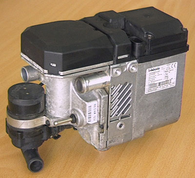
 SM038 - WEBASTO FUEL BURNING HEATER (CONFIG 1) - Diagnostic Capabilities (Read Fault Codes)