TEVES ATE MK20/MK25 - System Overview
MK20
A typical ABS ECU configuration, in that the ECU is assembled directly onto the valve block / pump assembly. Newly Introduced in 2000 this all in one small to luxury vehicle size ABS system was fitted to a large variety of different makes of vehicles, it was fitted to the Freelander in 2000 as part of the vehicle make over which was a dramatic change as the company had previously used only WABCO systems. Its use was however quite short lived as the manufactures discontinued it after only about a year in favour of a family of ECU’s to suit differing sized applications. Its replacement was nearly identical physically but was designated the MK25. It supports Traction control and Hill Descent control along with its normal ABS functionality, and is a very sophisticated system.

MK25
Replacing the MK20, this ECU and valve block / pump assembly is slightly lighter and utilises a very different diagnostic communication structure. It is one of a series of four family members all designed for different vehicle classes and situations.
SM043 - TEVES ATE MK20/MK25 - System Help file
Version 1.23

TEVES ATE MK20/MK25 - Known Fitments
Vehicle makes, models and variants known or believed to be using this vehicle system, required diagnostic lead and degree of known compatibility.

Vehicle Make Vehicle Model Vehicle Variant Diagnostic Lead
Land Rover Freelander 2001> Black OBDII Lead

TEVES ATE MK20/MK25 - Physical Details
MK20

MK25

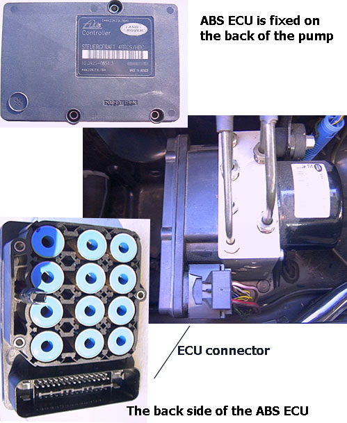
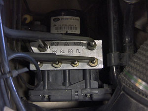
SM043 - TEVES ATE MK20/MK25 - Diagnostic Capabilities (Read Fault Codes)
Reads the fault code memory. The ECU can self detect up to 47 different problems with itself, its wiring and its associated sensors, storing the respective code if it detects any malfunction or reading outside of pre defined acceptable limits. Not all stored faults may cause the fault warning lamp to illuminate.

SM043 - TEVES ATE MK20/MK25 - Diagnostic Capabilities (Clear Fault Codes)
Clears the fault code memory.

SM043 - TEVES ATE MK20/MK25 - Diagnostic Capabilities (Settings)
Values, configuration settings, and other stored information which can be read from the ECU, edited and then rewritten back. Read settings can also be stored as a standard HTML page for reference. These pages can then later be re loaded and re written back to the ECU. Please note that some values may be read only due to the fact that they are supplied from the ECU’s ROM or are internally calculated.

  • Hardware Number: This is the hardware part number for the ECU.
  • Hardware Version: This is the hardware version which denotes the processor and circuit board type.
  • Coding Index: This is the coding identification for the programming maps.
  • Diagnostic Index: This is a number that indicates the diagnostic capabilities support level.
  • Year of Manufacture: This is the year in which the unit was built.
  • Week of Manufacture: This is the week in which the unit was built.
  • Day of Manufacture: This is the day in which the unit was built.
  • Supplier Code: This is a number which defines the supplier using a standard look up list of supplier ECU manufacturer numbers.
  • Software Version: This denotes the coding inside the processor for the hardware.
  • Coding Data: A specific block of programmable data stored in the ECU to control its functionality for specific variations of vehicle. There are a number of hexadecimal digits, each digit separated by a comma. Re-entered parameters should be entered in an identical format to that which is read. Changing these values can produce unknown alteration in the functionality of the ECU, damage the ECU, or even damage the vehicle.
  • VIN: Vehicle's identification number.

SM043 - TEVES ATE MK20/MK25 - Diagnostic Capabilities (Inputs)
Realtime live display of the information the electronic control unit of the selected vehicle system is currently deriving from its input sensors.

  • Instrument pack message status: This shows if the status of the CAN bus message from the Instrument Pack read by the ABS ECU is valid or invalid. For manual vehicles, this message contains information from the gear box.
  • G sensor (m/s²): This is the longitudinal acceleration returned by the 'G' sensor. Normal values are between -10 m/s² and +10 m/s².
  • Engine CAN message 1 status: This shows the status of the first of two CAN bus messages from the Engine Management ECU read by the ABS ECU. The message contains engine speed, torque and throttle switch information.
  • Engine CAN message 2 status: This shows the status of the second of two CAN bus messages from the Engine Management ECU read by the ABS ECU. The message contains throttle angle information.
  • Rear Left Wheel Speed: This is the speed of the rear left wheel as detected by the ABS ECU in kilometres per hour and miles per hour.
  • Front Left Wheel Speed: This is the speed of the front left wheel as detected by the ABS ECU in kilometres per hour and miles per hour.
  • Front Right Wheel Speed: This is the speed of the front right wheel as detected by the ABS ECU in kilometres per hour and miles per hour.
  • Rear Right Wheel Speed: This is the speed of the rear right wheel as detected by the ABS ECU in kilometres per hour and miles per hour.
  • Throttle position: This is the throttle pedal angle read by the ABS ECU via CAN from the Engine Management ECU.
  • Engine speed: This is the current engine speed in RPM read via CAN from the engine management ECU.
  • Max engine torques (%): This is the maximum engine torque read by the ABS ECU via CAN from the Engine Management ECU.
  • Friction torque loss: This is the frictional torque loss read by the ABS ECU via CAN from the Engine Management ECU.
  • Available Engine Torque: This is the available torque value as transmitted to the ABS ECU on the CAN bus by the engine management. The value is displayed as a percentage.
  • Gear Selector: This is the currently selected gear information sent to the ABS ECU via the CAN bus from the automatic gearbox ECU.
  • Reference voltage: Internal supply voltage in the ABS ECU. This value should be around 5V.
  • Battery Volts: This is the current battery voltage as read by the ABS ECU.
  • HDC Switch: Denotes the status of the hill descent control switch if it is pressed or released.
  • Brake Pedal: Denotes the status of the brakes if they are pressed or released.
  • Throttle pedal status: The state of the Throttle Pedal switch received by the ABS ECU via CAN from the Engine Management ECU.
  • Fluid Level: Denotes the status of the brake fluid level switch whether it is open or closed. When there is sufficient fluid it is closed and when it is low it is open.

SM043 - TEVES ATE MK20/MK25 - Diagnostic Capabilities (Outputs)


CAUTION: It is possible to damage ABS components by leaving them on for extensive periods of time of more than 10 or 15 seconds
VALVES
  • Front Right Inlet/ Front Right Outlet: The valve can be heard clicking.
  • Front Left Inlet/Front Left Outlet: The valve can be heard clicking.
  • Rear Right Inlet/Rear Right Outlet: The valve can be heard clicking.
  • Rear Left Inlet/Rear Left Outlet: The valve can be heard clicking.
  • Separation Valve: The valve can be heard clicking.
  • Shuttle Valve: The valve can be heard clicking.
OTHER
  • ABS Pump: The pump can be turned on.
  • ABS Warning Lamp: The LED will flash for 10 seconds.
  • TC Lamp: The LED will flash for 10 seconds.
  • HDC Info Lamp: The LED will flash for 10 seconds.
  • HDC Info Lamp: The LED will flash for 10 seconds.
  • HDC Brake Relay OFF: The brake lights will start flashing.
  • Brake Warning Lamp: The LED will flash for 10 seconds. Make sure that no brake is applied.
  • Speedo 50 mph: The speedometer needle will be forced to show 50 mph (80km/h).
There is a universal TURN ALL OUTPUTS OFF link which allows all outputs to be turned off after turning on.

SM043 - TEVES ATE MK20/MK25 - Diagnostic Capabilities (Other)
Choice of functions that can be performed.

  • Power Bleed: The process cycles the ABS pump and valves in order to clear the system of air. The air can be removed through the bleed screws. Fill the brake fluid reservoir, and make sure during the process that it is not empty. The relevant nipple needs to be open before initiating the test.
    • Power Bleed Front Brakes: The user will be required to instantly press and release the brake pedal and prompted when to not operate the brake pedal anymore and to close the valve. This requires two people.
    • Power Bleed Rear Brakes: The user will be required to instantly press and release the brake pedal and prompted when to not operate the brake pedal anymore and to close the valve. This requires two people.
    Repeat the operation 5 times, or until there are no air bubbles in the fluid.
  • Vac Fill: This function is provided as an aid to the Vacuum Fill process by opening the ABS valves that are normally closed. This requires the ignition to be on (position 2). The 4 outlet valves and the 2 reversing valves are forced to open for 1 second every 2 seconds.
  • Calibrate G Sensor: This operation has to take place every time when a new G sensor is fitted.