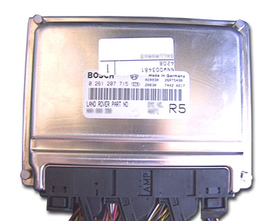
BOSCH ME7.2 - System Overview
Quite a sophisticated and modern Petrol Engine management system ECU. Manufactured by Bosch, and the latest in a long line of variations of the well known Motronic name, this ECU is also referred to in BMW terminology as DME Digital Motor Electronics. Being a flash based ECU with a huge memory the entire code that controls it’s operationally and functionality including its self diagnostic capability is determined by whatever version of software is programmed into it. Although Used extensively in many BMW models and some Porsches the system is also fitted into the petrol versions of the L322 Range Rover that are fitted with the BMW 4.4 Litre V8 engine, introduced in 2002 and was replaced in 2005 with a Denso unit employed by Ford who had purchased Land Rover from BMW to accompany their own Jaguar based engine. It is a modern enough ECU to fully support the limited degree of information and fault codes provided for by enforced OBDII compliance, but of course there many more fault codes, functions and features that this module gives access to beyond simple OBDII compatibility, including security link learning and re synchronization.
SM046 - BOSCH ME7.2 - System Help file
Version 1.27

BOSCH ME7.2 - Known Fitments
Vehicle makes, models and variants known or believed to be using this vehicle system, required diagnostic lead and degree of known compatibility.

Vehicle Make Vehicle Model Vehicle Variant Diagnostic Lead
Land Rover Range Rover MK III (L322) 2002 - Mid 2005 Black OBDII Lead/LD020/LD021
BMW 3 series (E36/E46) Unknown Unknown
BMW Z3 Unknown Unknown
BMW 7 series (E38) V8 Petrol 98 to 01 Unknown
BMW 5 series (E39) V8 Petrol 98 to 01 Unknown
BMW 8 series (E31) V8 Petrol 98 to 01 Unknown
BMW X5 (E53) V8 Petrol 98 to 01 Unknown
Porsche Boxster 3.2/3.4 Litre Unknown
Porsche 996 All Unknown
Porsche 7 series (E38) V8 Petrol Unknown

BOSCH ME7.2 - Physical Details


BOSCH EDC TD4 - Pin Outs
Details of the pin usage for the ECU connector(s).

C0331
1 Alternator warning lamp
2 Engine caranking signal
3 SAI pump relay
4 Cooling fan control unit
5 Not Used
6 Engine cranking signal
7 APP Sensor 1 ground
8 APP Sensor 1 signal
9 APP Sensor 1 supply
10 Fuel Pump relay
11 Not Used
12 APP Sensor 2 ground
13 APP Sensor 2 signal
14 APP Sensor 2 supply
15 and 16 Not Used
17 Engine speed signal
18 DMTL pump motor
19 Reverse gear signal
20 DMTL pump motor
21 LCM
22 Road Speed signal
23 Not used
24 Brake pedal switch
25 Not Used
26 Ignition power supply
27 Steering wheel Cruise Control switches
28 Brake pedal switch
29 A/C Compressor clutch disengage signal
30 DMTL changeover valve
31 Not Used
32 Diagnostic ISO 9141 K Line bus
33 Immobilisation signal
34 and 35 Not Used
36 CAN bus high (connection with main bus system)
37 CAN bus low (connection with main bus system)
38 Thermostat monitoring sensor ground
39 Thermostat monitoring sensor signal
40 Starter motor relay

C0332
1 Ignition coil 7 output
2 Ignition coil 8 output
3 Ignition coil 2 output
4 Ignition coil 3 output
5 Ignition ground
6 Ignition coil 1 output
7 Ignition coil 4 output
8 Ignition coil 5 output
9 Ignition coil 6 output

C0603
1, 2 and 3 Not used
4 Ground
5 Ground
6 Ground
7 Permanent battery power supply
8 Power supply from ECM relay
9 Not used

C0604
1 RH rear HO2S heater
2 Not used
3 CAN bus low (connection with EAT ECU)
4 CAN bus high (connection with EAT ECU)
5 and 6 Not used
7 LH rear HO2S heater
8 RH rear HO2S ground
9 LH front HO2S heater
10 RH front HO2S heater
11 LH rear HO2S ground
12 Not used
13 RH front HO2S heater
14 RH rear HO2S signal
15 LH rear HO2S signal
16 RH front HO2S signal
17 LH rear HO2S signal
18 Not used
19 LH front HO2S heater
20, 21 and 22 Not used
23 Main relay coil
24 Not used

C0606
1 Fuel injector 2
2 Fuel injector 3
3 Evap purge valve
4 and 5 Not used
6 Ground
7 MAF/IAT sensor power supply
8 Throttle position sensor 2 signal
9 MAF/IAT sensor ground
10 Throttle position sensors reference voltage
11 Not used
12 Starter motor feedback
13 Alternator charge signal
14 Fuel injector 7
15 Fuel injector 6
16 VCC solenoid valve 2
17 and 18 Not used
19 CMP sensor signal 2
20 CMP sensor signal 1
21 ECT sensor ground
22 ECT sensor signal
23 MAF/IAT sensor air flow signal
24 Throttle position sensor 1 signal
25 Throttle position sensor ground
26 Not used
27 Fuel injector 8
28 Fuel injector 5
29 VCC solenoid valve 1
30 Not used
31 Electric thermostat heater
32 CKP sensor signal
33 Not used
34 MAF/IAT sensor air temperature signal
35 Knock sensor cylinders 3 and 4 ground
36 Knock sensor cylinders 3 and 4 signal
37 Knock sensor cylinders 7 and 8 signal
38 Knock sensor cylinders 7 and 8 ground
39 Not used
40 Fuel injector 4
41 Fuel injector 1
42 Throttle position actuator 1
43 Throttle position actuator 2
44 Not used
45 CKP sensor ground
46 CKP sensor signal
47 Not used
48 Knock sensor cylinders 1 and 2 ground
49 Knock sensor cylinders 1 and 2 signal
50 Knock sensor cylinders 5 and 6 signal
51 Knock sensor cylinders 5 and 6 ground
52 SAI vacuum solenoid valve
SM046 - BOSCH ME7.2 - Diagnostic Capabilities (Read Fault Codes)
Reads the fault code memory. The ECU can self detect up to 47 different problems with itself, its wiring and its associated sensors, storing the respective code if it detects any malfunction or reading outside of pre defined acceptable limits. Not all stored faults may cause the fault warning lamp to illuminate.

SM046 - BOSCH ME7.2 - Diagnostic Capabilities (Clear Fault Codes)
Clears the fault code memory.

SM046 - BOSCH ME7.2 - Diagnostic Capabilities (Settings)
Values, configuration settings, and other stored information which can be read from the ECU, edited and then rewritten back. Read settings can also be stored as a standard HTML page for reference. These pages can then later be re loaded and re written back to the ECU. Please note that some values may be read only due to the fact that they are supplied from the ECU’s ROM or are internally calculated.

  • VIN Number: This is the vehicle identification number.
  • Assembly number: This is a unique number which defines the ECU hardware and software combination.
  • Part Number: This is the Bosch part number for this ECU.
  • Manufacturing Year: This year of manufacture of this ECU.
  • Manufacturing Week: The week of manufacture of this ECU.
  • Bus Index: The bus index for this ECU.
  • Diagnostic Index: The diagnostic index for this ECU.
  • Coding Index: The coding index for this ECU.
  • IDLE SPEED FOR THE FOLLOWING CONDITIONS:
    • Air Conditioning On Vehicle not in Drive or Reverse: This is the idle speed value the engine management ECU attempts to obtain when the air conditioning is on when the vehicle is not in drive or reverse.
    • Air Conditioning Off Vehicle not in Drive or Reverse: This is the idle speed value the engine management ECU attempts to obtain when the air conditioning is off when the vehicle is not in drive or reverse.
    • Air Conditioning On Vehicle in Drive or Reverse: This is the idle speed value the engine management ECU attempts to obtain when the air conditioning is on when the vehicle is not in drive or reverse.
    • Air Conditioning Off Vehicle in Drive or Reverse: This is the idle speed value the engine management ECU attempts to obtain when the air conditioning is off when the vehicle is not in drive or reverse.

SM046 - BOSCH ME7.2 - Diagnostic Capabilities (Inputs)
Realtime live display of the information the electronic control unit of the selected vehicle system is currently deriving from its input sensors.

GENERAL PAGE 1
  • Engine Roughness Cylinder 1 to 8: This shows the engine roughness value for cylinder (1 to 8).
  • O2 bank 1- 2: This reading shows the output voltage from the downstream bank 1 oxygen sensor. This voltage should normally be varying slowly over a period of several seconds. If this voltage is not varying there may be a problem with the sensor or with the catalyst. If this is the case a fault flag will almost always be set.
  • Closed Loop Bank 1/2: This shows if closed loop control is active on cylinder bank 1.
  • Ready Pre Cat Bank 1/2: This shows if the pre cat oxygen sensor on bank 1/2 is ready for lambda control. This will not appear as ready until specific operating conditions have been met. The meter should display ready when the engine is fully warm.
  • Ready Post Cat Bank 1/2: This shows if the post cat oxygen sensor on bank 1/2 is ready for lambda control. This will not appear as ready until specific operating conditions have been met. The reading should change to show ready when the engine is fully warm.
  • Idle Control: This shows if idle control is active. The value should change from Active to Non Active when the throttle pedal is pressed.
  • Full Load: This shows if the engine is operating at full load. This condition will only be seen under heavy load driving conditions.
  • Immobiliser: This shows if the vehicle is immobilised.
  • High Purge Load: This shows if there is a high EVAP purge load.
  • Fuel Cut Off: This shows if the safety fuel cut off has been activated. This will occur if an unknown or wrong throttle position is encountered.
  • Throttle Position Learned: This shows if the electronic throttle position has been learned.
  • Kick Down: This shows if the kick down switch is active.
  • Park/Neutral: This shows the auto gearbox park / neutral switch status.
GENERAL PAGE 2
  • Additive Adaption Bank 1/2: This shows the additive fuelling adaption for cylinder bank 1/2 expressed as a percentage.
  • Multiplicative Adaption Bank 1/2: This shows the multiplicative fuelling adaption for cylinder bank 1/2.
  • O2 Heating Pre Cat Bank 1/2: This shows the oxygen heating value for the pre cat sensor on cylinder bank 1/2.
  • O2 Heating Post Cat Bank 1/2: This shows the oxygen heating value for the post cat sensor on cylinder bank 1.
  • O2 Heating Period Bank 1/2: This shows the oxygen heater period for cylinder bank 1/2. It shows the period of time the heater is switched on.
  • Air leakage: This shows calculated air leakage through the intake path.
  • Equalisation: This shows the fast air mass flow equalisation factor.
  • Substitute Load: This shows the air mass flow substitute load factor.
  • Cam Adaption Cyl 1 to 8: This shows the camshaft adaptation value for cylinder X of the engine, measured in degrees.
GENERAL PAGE 3
  • Purge Valve Duty Cycle: This shows the current duty cycle ratio of the canister purge valve as a percentage. 100 % represents fully open.
  • Auxiliary Fan %: This shows the duty cycle for the auxiliary fans. A value of 93% means that the fan is off.
  • Secondary Air Valve: This shows the secondary air valve status.
  • Secondary Air Pump: This shows the secondary air pump status.
  • A/C Compressor: This shows the A/C compressor status.
  • Fuel Pump: This shows the fuel pump status.
  • Electric Thermostat: This shows the electric thermostat status.
  • Comfort Start: This shows if the comfort start function is active. The display should show Active if the key is turned to start the engine and immediately released.
  • O2 Heater Off Time Bank 1/2: This shows the oxygen sensor heater off time for cylinder bank 1/2. Typical value is 10 milliseconds.
  • Vanos Bank 1/2: This shows the duty cycle for the VANOS on cylinder bank 1/2.
  • Pre cat heater bank 1/2: This shows if the pre cat oxygen sensor heater on bank 1/2 is switched on.
  • Post cat heater bank 1/2: This shows if the post cat oxygen sensor heater on bank 1 is switched on.
GENERAL PAGE 4
  • Battery Condition: This shows the battery condition. The larger the number, the better the condition of the battery. A battery in good condition should give a value of around 18000, a value of 12000 or below indicates a poor battery. The value can be between -32.2768 and 32.2767.
  • Low Battery Load: This shows if the idle speed has been increased due to a low battery condition. This function should not be active if the battery condition value is above 18000.
  • A/C Load: This shows if the idle speed has been increased because the air conditioning is switched on. The target idle speed in this case would be 700 rpm.
  • Purge Load: This shows if the idle speed has been increased for high purge load.
  • Driver Demand Fault: This display will show if the brake pedal and throttle pedal have pressed at the same time during normal driving. The value displayed is the odometer reading in km at which the event occurred. This can be reset using the function found in the other section.
  • Cat Tested: This shows the state of catalytic converter diagnostic readiness flag. When Tested is displayed the oxygen sensor diagnostic has been carried out by the ECU.
  • O2 Pre: This shows the state of pre catalyst oxygen sensor diagnostic readiness flag. When Tested is displayed the oxygen sensor diagnostic has been carried out by the ECU.
  • O2 Post: This shows the state of post catalyst oxygen sensor diagnostic readiness flag. When Tested is shown the post catalyst oxygen sensor diagnostic has been carried out by the ECU.
  • Purge: This shows the state of purge system diagnostic readiness flag. When Tested is displayed the purge system diagnostic has been carried out by the ECU.
  • Secondary Air: This shows the state of secondary air system diagnostic readiness flag. When tested is displayed the secondary air system diagnostic has been carried out by the ECU.
GENERAL PAGE 5
  • Injector Timing: This shows the period of time for the ON injector pulse.
  • Target Idle Speed: This reading shows the target idle speed for the vehicle. The target idle speed is only valid when the engine is in idle. The value will change depending on engine load. The engine speed should not vary more than 50 rpm from the target idle speed.
  • O2 Control Bank 1-2: This shows lambda control status of cylinder bank 1/2. The value should nominally be 1 but typically will vary either side of 1 as part of the lambda control.
  • Engine Speed: This shows the engine speed in revolutions per minute. The speed is measured using the crankshaft sensor and flywheel. Idle speed control attempts to maintain the engine speed with 50 RPM of the target idle speed.
  • Road Speed: This is the vehicle road speed as measured by the ABS unit, it is passed to the ECM as a series of pulses. The ECM measures these pulses to calculate the vehicle road speed. The reading should be close to the value displayed on the instrument pack.
  • Cam Position Bank 1/2: This shows the position of the camshaft on bank 1/2 of the engine, measured in degrees.
  • Mass Air Flow: This shows the measured air mass flow rate in kilograms per hour. This reading shows the amount of air, which is being used by the engine. Under most conditions this will indicate the current power output of the engine.
  • Engine Torque %: This reading shows the current amount of torque being produced by the engine. The torque figure is expressed as a percentage of the maximum torque that can be produced by the engine. When the engine is fully warm and at idle this value should be around 9%.
  • Ignition Angle: This shows the ignition angle for cylinder 1 with respect to TDC. The meter bands show the expected value range on a fully warm engine under idle conditions.
  • Battery Voltage: This reading shows the vehicle battery voltage measured directly by the ECM. The meter bands show the normal range when the engine is running.
  • Throttle Position %: This shows the current percentage opening of the throttle position sensor. This percentage varies with the position of the throttle pedal between close to zero with the throttle closed to about 100% at fully open throttle.
  • Intake Air Temperature: This shows the current temperature of the air at the engine air intake. The measurement is taken using the intake air temperature sensor.
  • Coolant Air Temperature: This shows the current temperature as read by the engine coolant temperature sensor.
  • Radiator Coolant Temperature: This shows the current temperature as read by the radiator outlet coolant temperature sensor. Due to the way that the thermostat control affects the radiator coolant temperature, it is not possible to define fixed operating limits.
  • Driver Demand Voltage: This shows the current value of the throttle pedal potentiometer. The voltage varies with the position of the throttle pedal between close to zero with the throttle closed to about 4.6V at fully open throttle.
  • Knock Sensor 1 to 8: This shows the normalised voltage threshold for cylinder 1 to 8. It should be monitored at idle and when the engine is fully warm.
SWITCHES
The cruise switches display shows the status of the cruise control switches on the steering wheel.
  • Cruise Master Button: This shows the state of the cruise control main switch, located on the steering wheel.
  • Cruise System Status: This shows the state of the cruise control.
  • Cruise Lamp: This shows the state of the cruise control lamp.
  • Cruise Acceleration Button: This shows the state of the cruise control acceleration (+) switch, located on the steering wheel.
  • Cruise Deceleration Button: This shows the state of the cruise control deceleration (-) switch, located on the steering wheel.
  • Cruise Set Status: This shows the state of the cruise control set switch, located on the steering wheel.
  • Brake Switch: This shows the state of the brake switch. It should change state if the brake pedal is pressed.
  • Brake Safety Switch: This shows the state of the brake safety switch. It should change state if the brake pedal is pressed.
  • Cruise Resume: This shows the state of the cruise control resume switch, located on the steering wheel.
  • A/C Request: This shows the state of the A/C request switch.
  • Cranking: This shows the state of the cranking functionality of the ECU. It should read ON during cranking and OFF at any other time.
  • Ignition Stage II: This shows the state of the ignition switch, it should show ON when it is in position 2.

SM046 - BOSCH ME7.2 - Diagnostic Capabilities (Outputs)
  • Cooling Fan: Sets the cooling fan for 45 seconds to fast, medium, or slow speed.
  • Secondary Air Pump: Turns the air pump in pulses on and off for 15 seconds.
  • Purge Valve: Pulses the purge valve on and off for 15 seconds. It is possible to hear the valve ticking.
  • Fuel Pump: Pulses the fuel pump on and off for 30 seconds.
  • Starter Relay: This is direct engagement of the starter relay for 1 second. The vehicle may start and if starts, it is possible the starter motor may remain engaged and therefore require the ignition switch to be turned off.
    Caution: engine might start, car might move, the starter motor can stay engaged - ensure car is out of gear and hands and objects are free from moving parts.
  • A/C Clutch: This pulses the A/C clutch on and off for 10 seconds.
  • Injectors 1 - 8: This pulses the injector on and off for 10 seconds. It should be noted that the injectors are very quiet in this engine and it is very difficult to hear them ticking.
  • O2 Heater Pre catalyst Converter Bank 1: This turns on the heater element in the oxygen sensor before the catalyst on Bank 1.
  • O2 Heater Pre catalyst Converter Bank 2: This turns on the heater element in the oxygen sensor before the catalyst on Bank 2.
  • O2 Heater Post Catalyst Converter Bank 2: This turns on the heater element in the oxygen sensor after the catalyst on Bank 1.

SM046 - BOSCH ME7.2 - Diagnostic Capabilities (Other)
  • Start Synchronization with immobiliser ECU: This causes the engine management ECU to go into Learn Mode where it will learn the next output from the immobiliser ECU and synchronize with it.
    The synchronization procedure is done in three steps that should take place in one ignition cycling.
    1. Put the engine management in learning mode: This function is to be found in the engine management START SYNCHRONIZATION WITH IMMOBILISER ECU. The function will set the ECU into learning mode. Once you've been prompted that the engine management is in learning mode, navigate in the Vehicle Explorer to the immobiliser for step 2.
    2. Send code from immobiliser ECU: This function is to be found in the immobiliser SYNCRONIZE WITH ENGINE MANAGEMENT SYSTEM. This function will send codes to be learned. Once you've been prompted that the immobiliser sent the code successfully, navigate in the Vehicle Explorer to the engine management for step 3.
    3. Take the engine management out of learning mode: This function is to be found in the engine management END SYNCHRONIZATION WITH IMMOBILISER ECU. The function will end the learning mode, leaving the ECU in normal mode.
  • End Synchronization with immobiliser ECU: This causes the engine management ECU to acknowledge the code sent by the immobiliser ECU and to exit Learn Mode.
  • Reset Adaptation Values: This forces the engine management to reset all currently learned adaptation values to default values. The engine will run slightly rougher after this, but new values will quickly be re-learnt.
  • Driver Demand Reset: This forces a reset of the driver demand error value. This is caused when the accelerator and brake are pressed at the same time.
  • Temporary Idle Speed: Control of the idle speed can be tested by causing the ECU to temporarily adjust the idle speed off the standard idle speed using one of the buttons provided. Up to a maximum of plus or minus 500 rpm in 50 rpm stages.