WABCO EAS (NGRR) - System Overview
Only a small plastic box with two connectors on it fitted to All L322 Range Rovers, but this is one giant leap over the system used in the P38.
SM048 - WABCO EAS (NGRR) - System Help file
Version 1.27

WABCO EAS (NGRR) - Known Fitments
Vehicle makes, models and variants known or believed to be using this vehicle system, required diagnostic lead and degree of known compatibility.

Vehicle Make Vehicle Model Vehicle Variant Diagnostic Lead
Land Rover Range Rover MK III (L322) 2002 - Mid 2005 Black OBDII Lead/LD020/LD021

WABCO EAS (NGRR) - Physical Details


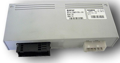
Waboc EAS - Pin Outs
Details of the pin usage for the ECU connector(s).

C0867
1 Not used
2 CAN bus high
3 Control switch up selection
4 Control switch hold selection
5 Control switch motorway ride height LED
6 Front RH corner valve control
7 Front LH and RH conrner control valves power supply
8 Front LH corner valve control
9 Rear RH corner valve control
10 Rear LH and RH corner valves power supply
11 Rear LH conrner control valve
12 Reservoir valve control input
13 Reservoir valve power supply
14 Exhaust pilot valve power supply
15 Exhaust pilot valve control
16 Air suspension relay control
17 High pressure exhaust valve power supply
18 Not used
19 Not used
20 CAN bus low
21 Control switch down selection
22 Control switch off-road ride height LED
23 Control switch access ride height LED
24 Front RH height sensor signal
25 Front LH height sensor signal
26 Rear RH height sensor signal
27 Rear LH height sensor signal
28 Air pressure sensor signal
29 Not used
30 Not used
31 Temperature sensor
32 Front LH height sensor power supply
33 Front RH height sensor power supply
34 Air pressure sensor power supply
35 High pressure exhaust valve control
36 Not used
37 K Bus
38 Wake up signal
39 Ride height switch (on driver's door module)
40 Control switch standard ride height LED output
41 Control switch hold switch LED
42 Front RH height sensor ground
43 Front LH height sensor ground
44 Rear RH height sensor ground
45 Front LH height sensor ground
46 Air pressure sensor ground
47 Not used
48 Not used
49 Temperature sensor ground
50 Rear RH height sensor power supply
51 Rear LH height sensor power supply
52 Not Used
53 Not Used
54 Not Used
C02030
1 Not used
2 Front cross link valve ground (if fitted)
3 Rear cross link valve ground
4 Not used
5 Ground
6 Not used
7 Rear cross link valve power supply
8 Front cross link valve power supply (if fitted)
9 Not used
10 Battery power supply

SM048 - WABCO EAS (NGRR) - Diagnostic Capabilities (Read Fault Codes)
Reads the fault code memory. The ECU can self detect up to 52 different problems with itself, its wiring and its associated sensors, storing the respective code if it detects any malfunction or reading outside of pre defined acceptable limits. Not all stored faults may cause the fault warning lamp to illuminate.

SM048 - WABCO EAS (NGRR) - Diagnostic Capabilities (Clear Fault Codes)
Clears the fault code memory.

SM048 - WABCO EAS (NGRR) - Diagnostic Capabilities (Settings)
Values, configuration settings, and other stored information which can be read from the ECU, edited and then rewritten back. Read settings can also be stored as a standard HTML page for reference. These pages can then later be re loaded and re written back to the ECU. Please note that some values may be read only due to the fact that they are supplied from the ECU’s ROM or are internally calculated.

  • Part Number: This is the manufacturer's part number for the ECU.
  • Hardware Number: This is the hardware version which denotes the processor and circuit board type.
  • Software Number: This denotes the coding inside the processor for the hardware.
  • Supplier Number: This is a number which defines the supplier, using a standard look up list of supplier ECU manufacturer numbers.
  • Coding Index: This is the coding identification for the programming maps.
  • Diagnostic Index: This is a number that indicates the diagnostic capabilities support level.
  • Bus Index: This is a number that indicates the bus communication support level, the vehicle communication buses.
  • Week of Build: This is the week in which the unit was built.
  • Year of Build: This is the year in which the unit was built.
  • Front Left Height: This is a numerical value which is not related to any specific known measurements increments i.e. inches or millimetres that directly affect the height of the car. Each increment is worth approximately half a millimetre and the normal ranges go between a few 100 up to below 1000 going beyond these values can have unexpected results causing the system to lock requiring the fault code memory to be cleared for the range to once again return to normal standard.
  • Front Right Height: This is a numerical value which is not related to any specific known measurements increments i.e. inches or millimetres that directly affect the height of the car. Each increment is worth approximately half a millimetre and the normal ranges go between a few 100 up to below 1000 going beyond these values can have unexpected results causing the system to lock requiring the fault code memory to be cleared for the range to once again return to normal standard.
  • Rear Left Height: This is a numerical value which is not related to any specific known measurements increments i.e. inches or millimetres that directly affect the height of the car. Each increment is worth approximately half a millimetre and the normal ranges go between a few 100 up to below 1000 going beyond these values can have unexpected results causing the system to lock requiring the fault code memory to be cleared for the range to once again return to normal standard.
  • Rear Right Height: This is a numerical value which is not related to any specific known measurements increments i.e. inches or millimetres that directly affect the height of the car. Each increment is worth approximately half a millimetre and the normal ranges go between a few 100 up to below 1000 going beyond these values can have unexpected results causing the system to lock requiring the fault code memory to be cleared for the range to once again return to normal standard.
  • Coding Data: A specific block of programmable data stored in the ECU to control its functionality for specific variations of vehicle. There are a number of hexadecimal digits, each digit separated by a comma. Re-entered parameters should be entered in an identical format to that which is read. Changing this values can produce unknown alteration in the functionality of the ECU, damage the ECU, or even damage your car.

SM048 - WABCO EAS (NGRR) - Diagnostic Capabilities (Inputs)
Realtime live display of the information the electronic control unit of the selected vehicle system is currently deriving from its input sensors.

GENERAL
  • Battery Volts: This is the power supply battery voltage to the air suspension ECU.
  • Wake Up Volts: This is the voltage on diagnostic line which it uses for communication to wake up.
  • Pressure Sensor Volts: This is the voltage being obtained from the pressure sensor.
  • Compressor Temperature Volts: This is the voltage being obtained from the compressor temperature sensor.
  • Front Right and Rear Left Height Sensor Supply Volts: This is the voltage being supplied to front right and rear left height sensors.
  • Front Left and Rear Right Height Sensor Supply Volts: This is the voltage being supplied to front left and rear right height sensors.
  • Pressure Sensor Supply Volts: This is the voltage being applied to the pressure sensor.
  • Front Right Height Sensor Supply Volts: This is the voltage being returned from the front right height sensor.
  • Front Left Height Sensor Supply Volts: This is the voltage being returned from the front left height sensor.
  • Rear Right Height Sensor Supply Volts: This is the voltage being returned from the rear right height sensor.
  • Rear Left Height Sensor Supply Voltage: This the voltage being return from the rear left height sensor.
  • Front Right Height (mm): This is an internally calculated figure that the ECU uses for its own reference for its own calculations. This does not necessarily refer to any external variations and should not be considered when calculating adjustments.
  • Front Left Height (mm): This is internally calculated figure that the ECU uses for its own reference for its own calculation. This does not necessarily refer to any external variations and should not be considered when calculating adjustments.
  • Rear Right Height (mm): This is internally calculated figure that the ECU uses for its own reference for its own calculation. This does not necessarily refer to any external variations and should not be considered when calculating adjustments.
  • Rear Left Height (mm): This is internally calculated figure that the ECU uses for it's own reference for its own calculation. This does not necessarily refer to any external variations and should not be considered when calculating adjustments.
  • Front Right Valve: This shows the status of the front right valve connected to the air spring on the front right hand corner of the car, with the status of either open or closed. When open, air is allowed to flow in or out of this air spring and when closed its not.
  • Front Left Valve: This shows the states of the front Left valve connected to the air spring on the front left hand corner of the car, with the status of either open or closed. When open air is allowed to flow in or out of the air spring and when closed it's not.
  • Rear Right Valve: This shows the status of the rear right valve connected to the air spring on the rear right hand corner of the car, with the status of either open or closed. When open, air is allowed to flow in or out of the air spring and when closed its not.
  • Rear Left Valve: This shows the status of the rear Left valve connected to the air spring on the rear left hand corner of the car, with the status of either open or closed. When open, air is allowed to flow in or out of the air spring and when closed its not.
  • Compressor Temperature: This is the current temperature value for the compressor. This is not in any normal unit values and being only a representational value, averages about 40 when normal.
  • Wake Up: This denotes if the ECU is awake or not.
  • Compressor Relay: This denotes if the air suspension is turning on the compressor or not.
  • Reservoir Pressure: This is a representation of the pressure in the reservoir.
  • Inhibit Switch: This denotes whether the air suspension motion inhibit switch is pressed or not.
  • Access Button: This denotes if the door mounted access button is pressed or not.
  • Up Switch: This denotes if the rotary control has been rotated to the up position.
  • Down Switch: This denotes if the rotary control has been rotated to the down position.
  • Standard LED: This denotes if the LED for standard mode is on or off.
  • Off Road LED: This denotes if the LED for Off Road mode is on or off.
  • Access LED: This denotes if the LED for Access mode is on or off.
  • Inhibit LED: This denotes if the LED for Hold mode is on or off.
  • Motorway LED: This denotes if the LED for Motorway mode is on or off.
  • Exhaust Valve: This denotes if the exhaust valve is open or closed. This is the valve which vents air from any of the corners to the atmosphere.
  • Reservoir Valve: This denotes if the reservoir valve is open or closed. If it is open pressure from the reservoir will flow into any open air spring.
  • High Pressure Exhaust Valve: This denotes if the high pressure exhaust valve opens which prevents a higher flow of air to escape the system.
  • Rear Cross Link Valve: This is the valve that allows a flow of air from one side of the vehicle to the other. It can be either open or closed. This valve is not fitted on later models of vehicle. This can be determined by analysing the SA Code.
  • Front Cross Link Valve: This is the valve that allows a flow of air from one side of the vehicle to the other. It can be either open or closed. This valve is not fitted on later models of vehicle. This can be determined by analysing the SA Code.
HEIGHTS
  • Standard Offset Height: This is the difference between the height when set to standard mode and the stored height settings.
  • Motorway Offset Height: This is the difference between the height when set to motorway mode and the stored height settings.
  • Access Offset Heights: This is the difference between the heights when set to access mode and the stored height settings.
  • Off Road Offset Height: This is the difference between the heights when set to off road mode and the stored height settings.
  • Below Height Tolerance Ign On: This is the amount that the air suspension ECU will allow for the current height to be below the target height while the ignition is on.
  • Below Height Tolerance Ign Off: This is the amount that the air suspension ECU will allow for the current height to be below the target height while the ignition is off.
  • Above Height Tolerance Ign On: This is the amount that the air suspension ECU will allow for the current height to be above the target height while the ignition is on.
  • Above Height Tolerance Ign Off: This is the amount that the air suspension ECU will allow for the current height to be above the target height while the ignition is off.
  • Axle Offset: This is the amount that it will allow shifted on the same axle.
  • Maximum Pressure Reservoir: This is a numerical value which sets a limit for the maximum pressure allowed to accumulate in the reservoir.
  • Target Pressure Reservoir: This is a numerical value which is the amount that is aiming for.
  • Minimum Pressure Reservoir: This is the minimum amount of pressure before the air suspension ECU switches on the compressor.
  • Over Temperature Filling: This is the status of the ECU in respect of its limits set for reservoir filling: enabled or disabled as previously defined.
  • Over Temperature Regulation: This is governing the vehicle lifting and lowering.
  • Dynamic Stability Control: This is OK or NOT OK depending if the communications from the stability control indicate that the stability control is functional or not.
  • Over Volts: This indicates if the air suspension ECU is over voltage.
  • Under Volts: This indicates if the air suspension ECU is under voltage.
  • Access Height Disable Temperature: This is a preset temperature above which the air suspension will not go into access height.
  • Reservoir Filling Disable Temperature: This is a compressor temperature after which the air suspension will no longer fill the reservoir.
  • Reservoir Filling Enable Temperature: This is a temperature below which the air suspension will continue to fill the reservoir.
  • Compressor Lifting Disable Temperature: This is the temperature at which the air suspension compressor will no longer operate in order to raise the height of the car.
  • Compressor Lifting Enable Temperature: This is the temperature below which the air suspension compressor will operate in order to enable the raising of the car.
  • Carlift Jack Regulation Inhibit: This denotes if the air suspension normal high regulation function is inhibited as a result of the air suspension detecting that the vehicle is being lifted with a car jack.
  • Door Open Regulation Inhibit: This denotes if the air suspension normal regulation function is being inhibited as a result of a door being detected as open.
  • Valve Duty Cycle Regulation Inhibit: This denotes if the air suspension normal regulation function is being inhibited as a result of the valves exceeding their normal duty cycle ratio.
  • Braking Regulation Inhibit: This denotes if the air suspension is being inhibited from operating its normal regulation function as a result of lengthy braking.
  • Average Height Regulation Inhibit: This denotes if the air suspension regulation is being inhibited as a result of the vehicle being at an average height of the differences.
  • Up Regulation: This denotes if the air suspension ECU is regulating the vehicle's height in an upwards direction.
  • Down Regulator: This denotes if the air suspension ECU is regulating the vehicle's height in an downwards direction.
  • Engine Management ECU Status: This denotes if the engine management has informed the air suspension if it has any functional problems.
  • Instrument Pack ECU status: This denotes if the air suspension ECU has been informed by the instrument pack if it has any functional problems.

SM048 - WABCO EAS (NGRR) - Diagnostic Capabilities (Outputs)
Choice of outputs that can be tested.

Note: more than one valve can be opened at any one time so that any combination of air springs can be inflated or deflated.
  • Front Right Valve: It is possible to open and close the valve.
  • Front Left Valve: It is possible to open and close the valve.
  • Rear Right Valve: It is possible to open and close the valve.
  • Rear Left Valve: It is possible to open and close the valve.
  • Front/Rear Cross Link Valve: These valves do not exist on later vehicles. This is denoted by the configuration identification in the SA code.
  • Compressor: This can be turned on or off.
  • High Pressure Exhaust Valve: This can be opened or closed.
  • Reservoir Valve: This can be opened or closed.
  • Exhaust Valve: This can be opened or closed. This opens the exhaust valve which allows airflow from any open spring to the atmosphere.
  • Standard LED: Can be turned ON or OFF.
  • Motorway LED: Can be turned ON or OFF.
  • Off Road LED: Can be turned ON or OFF.
  • Access LED: Can be turned ON or OFF.
  • Inhibit LED: Can be turned ON or OFF.

SM048 - WABCO EAS (NGRR) - Diagnostic Capabilities (Other)
Choice of functions that can be performed.

ATTENTION: Before any disassembly work commences on any part of the air suspension system it is critically important to ensure that the high pressure that normally fills the system is completely removed. This function enables this to be carried out. Failure to ensure that the system has fully de-pressurised can result in serious personal injury.
  • Read Transport / Production Mode: This allows the current transportation and production mode to be verified.
  • Set Transportation Mode: This allows the transportation mode to be set where the vehicle will no longer adjust its height. The vehicle will lower when the ignition is turned off. Make sure the vehicle is not obstructed as the riding heights might change.
  • Clear Transport Mode: This allows the transport mode lock to be cleared. The vehicle will raise when the ignition is turned on. This might take some time if the air suspension compressor is hot or the reservoir is empty.
  • Clear Production Mode: This allows the production mode lock to be cleared. A new ECU is delivered in production mode and needs clearing before use. All faults should be cleared in the air suspension system. Ensure steering angle sensor is initialised.
  • Store Current Heights: This makes the vehicle take the heights which it is currently at and store them as its standard default heights from which every other height is referenced.