Realtime live display of the information the electronic control unit of the selected vehicle system is currently deriving from its input sensors.
- Coolant Temperature (°C): This displays the coolant temperature as measured by the ECU. The value should rise smoothly during the engine warm up from the ambient temperature to approximately 85°C. A faulty temperature sensor may cause poor starting, fuel consumption, fast idle speed and cooling fans to run continuously.
- Oil Temperature (°C): This displays the oil temperature measured by the ECU. The value should rise smoothly during the engine warm up from the ambient temperature to approximately 85°C. A faulty temperature sensor may cause fuelling and idle speed problems.
- Inlet Air Temperature (°C): This displays the temperature measured by the ECU using the inlet air temperature sensor. The inlet air temperature is used by the ECU to retard the ignition timing to avoid knock and trim the fuelling when hot. If the sensor is not operating correctly the engine performance may be impaired slightly.
- Ambient Temperature (°C): This displays the ambient temperature in the engine bay measured by the ECU using the ambient air temperature sensor. This is done to control an extra engine bay cooling fan on vehicles which require this. A faulty temperature sensor will effect the normal operation of the cooling fan.
- Fuel Rail Temperature (°C): This displays the temperature measured by the ECU using the fuel rail temperature sensor. This reading is used by the ECU to make correction to fuelling and as an aid to hot starting. A faulty sensor can alter the performance of the engine and hot starting.
- Manifold Pressure (KPa): This displays the pressure measured by the external MEMS air pressure sensor. Normal reading with the engine not running is approximately 100 KPa and 30-40 KPa when the engine is idling. Very high values may indicate problems with the sensor or a blocked or disconnected vacuum pipe. Moderately raised values may indicate mechanical problems with the engine.
- Throttle Angle (deg): This displays the position of the throttle disc obtained from the MEMS ECU using the throttle potentiometer. This value should change from a low value to a high value as the throttle pedal is depressed. Accepted values are between 0 and 369 deg.
- Throttle Status: This displays the status of the throttle position as received from the throttle position sensor. If the switch shows open when the throttle is closed then the vehicle will not idle correctly and the closed throttle position may need to be reset.
- Feedback (Oxygen Sensor Feedback Correction: Display of the current feedback fuelling correction. This is shown as a percentage of the mapped (open loop) value. This percentage is continuously updated by the MEMS ECU whenever the conditions for closed loop fuelling are present. Other times the feedback value will show 100% indicating that closed loop fuelling is not operational. High values of feedback (e.g.120%) indicate that feedback is at tempting to compensate for fuelling being too lean and low values (e.g.80%) for fuelling being too rich. Note: Misfire condition will be shown as high values as feedback will be fooled into compensating for a system running too lean. There are two values shown the first is for single sensor configurations or Bank 1 in dual bank configurations and the second is for Bank 2 and will show as 0 in single bank configurations.
- Oxygen Sensor: These values show the voltage across the oxygen sensors as read by the MEMS ECU. Once the engine is fully warm, during most idle and driving condition this voltage will be alternating from above 2.025v to below 1.575v. The sensor detects the presence or absence of oxygen in the exhaust gas. When the exhaust gas has oxygen present the ECU will read a low voltage.
There are two values shown, the first one displays the voltage of the single sensor in single sensor configurations or the sensor serving bank 1. The second voltage is the Bank 2 sensor and is only active in dual sensor configurations. This always reads zero in single sensor configurations.
- Feedback States: This shows whether the fuelling is being controlled using feedback from the oxygen sensors. On a fully warm vehicle, the fuelling should be ACTIVE under most driving and idling conditions. There are two values shown, the first one displays the feedback state of the ECU in single sensor configurations or the feedback state of bank 1 on dual bank (2 sensor) configurations. The second displays the feedback control state of Bank 2 and is only active in dual bank (2 sensor) configurations. This always reads OPEN in single sensor configurations.
- Required Cam Period: This display the cam period that the MEMS ECU is trying to achieve for a set of given driving conditions. If the required and measured cam period do not closely correspond this may indicate possible faults with the Vi mechanism.
- Measured Cam Period: This displays the current cam period as measured by the MEMS ECU. If the required and measured cam period do not closely correspond this may indicate possible faults with the Vi mechanism.
- Ignition Switch: This shows the state of the ignition switch as read by the MEMS ECU.
- A/C Switch: This shows the state of the air condition request signal at the MEMS ECU. This signal depends on the state of the air condition switch, the blower fan control, the air con thermal switch and the trinary high/low pressure switch. The ECU will not show air con on unless all of these switches are on. The thermal switch will be off if the temperature of the air leaving the evaporator is less than about 3 C and the high/low pressure switch will be off if the pressure of the refrigerant is too high or too low.
- Drive Switch: This reading is valid only for vehicles with automatic transmission. This shows the measured state of the Park/Neutral switch. This switch is used to improve the quality of engine idle speed control on automatic gearbox vehicles. A fault with this switch will cause the idle speed to dip or rise suddenly when the gear selection is changed between neutral and drive.
- Fan Request: This shows the ECU fan request input. This input will be active if the air condition trinary medium pressure switch is closed requesting that the ECU fan control is set to maximum (fans on high speed).
- Battery Voltage: This shows the voltage of the vehicle supply measured internally by the ECU. Large errors in this measurement will lead to possible poor starting and errors in idle CO.
- Crankshaft Synchronisation: This shows the state of the crank. This should read SYNCRONIZED when the engine is running.
- Camshaft Synchronization: This shows the state of the cam. This should read SYNCRONIZED when the engine is running.
- Stepper Position (steps): This shows the position of the IACV stepper motor as calculated by the ECU. The ECU has no method of actually measuring this position but instead works it out by remembering how may steps it has moved the steppers since the last time the ignition was switched off. If a stepper motor fault exists this number will be incorrect. This value will normally be changing during idle conditions the ECU makes minor changes to the idle speed. A value of 0 during idle conditions indicates a fault condition or poor adjustment as does a very high value.
- Engine Speed: This shows the rotational speed of the engine, calculated by the MEMS ECU using the crankshaft sensor. Faults in the crankshaft sensor or associated wiring may be indicated if this display reads 0 during engine cranking.
|
 SM072 - LUCAS MEMS 2J - System Help file
 LUCAS MEMS 2J - Known Fitments
 LUCAS MEMS 2J - Physical Details
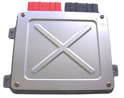
 LUCAS MEMS 2J - Pin Outs