Details of the pin usage for the ECU connector(s).
| C0331 |
 |
| 1 |
Alternator warning lamp |
| 2 |
Engine cranking signal |
| 3 |
Not used |
| 4 |
Cooling fan control unit |
| 5 and 6 |
Not used |
| 7 |
APP sensor 1 ground |
| 8 |
APP sensor 1 signal |
| 9 |
APP sensor 1 supply |
| 10 |
Fuel pump relay output |
| 11 |
Oil pressure signal |
| 12 |
APP sensor 2 ground |
| 13 |
APP sensor 2 signal |
| 14 |
APP sensor 2 supply |
| 15 and 16 |
Not used |
| 17 |
Diagnostic socket ground |
| 18 |
Not used |
| 19 |
Reverse gear signal |
| 20 |
Not used |
| 21 |
LCM |
| 22 |
Road speed signal |
| 23 |
Not used |
| 24 |
Brake pedal switch |
| 25 |
Not used |
| 26 |
Ignition power supply |
| 27 |
Steering wheel cruise control switches |
| 28 |
Brake pedal switch |
| 29 |
A/C compressor clutch disengage signal |
| 30 and 31 |
Not used |
| 32 |
Diagnostic ISO 9141 K line bus |
| 33 |
Immobilisation signal |
| 36 |
CAN bus high (connection with main bus system) |
| 37 |
CAN bus low (connection with main bus system) |
| 38 to 40 |
Not used |
| C0332 |
|
| 1 |
Feed to fuel injectors 4, 5 and 6 |
| 2 |
Not used |
| 3 |
Ground for fuel injector 6 |
| 4 |
Feed to fuel injectors 1, 2 and 3 |
| 5 |
Ground for fuel injector 1 |
| 6 |
Ground for fuel injector 4 |
| 7 |
Ground for fuel injector 2 |
| 8 |
Ground for fuel injector 3 |
| 9 |
Ground for fuel injector 5 |
| C0603 |
|
| 1 |
Power supply from main relay |
| 2 and 3 |
Not used |
| 4 |
Ground |
| 5 |
Ground |
| 6 |
Ground |
| 7 |
Not used |
| 8 |
Power supply from main relay |
| 9 |
Main relay coil |
| C0604 |
|
| 1 and 2 |
Not used |
| 3 |
CAN bus low (connection with EAT ECU) |
| 4 |
CAN bus high (connection with EAT ECU) |
| 5 |
Not used |
| 6 |
Diagnostic ISO 9141 K line bus |
| 7 |
Not used |
| 8 |
Engine mount damping control actuator |
| 9 |
Low fuel pressure sensor supply |
| 10 |
Low fuel pressure sensor ground |
| 11 to 16 |
Not used |
| 17 |
Low fuel pressure sensor signal |
| 18 to 24 |
Not used |
| C0606 |
|
| 1 |
MAF/IAT sensor power supply |
| 2 |
MAF/IAT sensor air flow signal |
| 3 |
MAF/IAT sensor ground |
| 4 |
CMP sensor signal |
| 5 |
Not used |
| 6 |
CKP sensor signal |
| 7 to 9 |
Not used |
| 10 |
EGR solenoid (modulator) |
| 11 |
Fuel temperature sensor signal |
| 12 |
Glow plug relay control |
| 13 |
Not used |
| 14 |
Boost pressure sensor power supply |
| 15 |
Boost pressure sensor signal |
| 16 |
Boost pressure sensor ground |
| 17 |
CMP sensor ground |
| 18 |
Fuel temperature sensor ground |
| 19 |
CKP sensor screen ground |
| 20 |
Fuel rail pressure sensor ground |
| 21 and 22 |
Not used |
| 23 |
Boost pressure regulator |
| 24 to 27 |
Not used |
| 28 |
ECT sensor signal |
| 29 |
MAF/IAT sensor air temperature signal |
| 30 |
Not used |
| 31 |
CKP sensor ground |
| 32 |
ECT sensor ground |
| 33 |
Fuel rail pressure sensor signal |
| 34 |
Not used |
| 35 |
Fuel rail pressure power supply |
| 36 and 37 |
Not used |
| 38 |
Fuel rail pressure control valve |
| 39 and 40 |
Not used |
| 41 |
Oil pressure switch signal |
| 42 to 49 |
Not used |
| 50 |
Alternator charge signal |
| 51 |
Engine start signal feedback |
| 52 |
Glow plug relay fault status |
 SM073 - BOSCH DDE4 TD6 - Diagnostic Capabilities (Read Fault Codes) SM073 - BOSCH DDE4 TD6 - Diagnostic Capabilities (Read Fault Codes) |
| Reads the fault code memory. The ECU can self detect up to 42 different problems with itself, its wiring and its associated sensors, storing the respective code if it detects any malfunction or reading outside of pre defined acceptable limits. Not all stored faults may cause the fault warning lamp to illuminate. |
| SM073 - BOSCH DDE4 TD6 - Diagnostic Capabilities (Clear Fault Codes) |
| Clears the fault code memory. |
| SM073 - BOSCH DDE4 TD6 - Diagnostic Capabilities (Settings) |
Values, configuration settings, and other stored information which can be read from the ECU, edited and then rewritten back. Read settings can also be stored as a standard HTML page for reference. These pages can then later be re loaded and re written back to the ECU. Please note that some values may be read only due to the fact that they are supplied from the ECU’s ROM or are internally calculated.
DDE4 TD6 SETTINGS / INFORMATION
- Week of Build: This shows the manufacturing week of the ECU.
- Year of Build: This shows the manufacturing year of the ECU.
- Part Number: This is the manufacturer's part number for the ECU.
- Hardware Number: This is the hardware version which denotes the processor and circuit board type.
- Coding Index: A numerical value which is read from the ECU. It is the coding identification for the programming maps.
- Diagnostic Index: A numerical value which is read from the ECU. This number indicates the diagnostic capabilities support level.
- Bus Index: The bus index which is read from the ECU. This indicates the bus communication support level on the vehicle communication buses.
- Idle Speed: This is the idle speed of the engine.
DDE4 TD6 PROGRAMMING DATA
New Record Entry / Active Record- Areas where new programming data can be entered and current data can be read.
- VIN Number: Vehicle's identification number.
- Programming Date: This is the recorded date on which the ECU was programmed.
- Assembly Number: This is a unique number which defines the ECU hardware and software combination.
- Homolog. Number: This is the recorded emission control test number (Homologation) which is allocated to the ECU configuration/fuel tune map set by the respective authority.
- Programming Station: This is a code by which the programming equipment may be recognised. The programming may be done at a number of stages during the life of the ECU by different programming equipment. The most common code is T9999; this denotes Land Rovers own TestBook equipment. X codes usually refer to Bosch programming equipment and are often seen in the 1st record which is created during manufacture.
- Odometer (Km): When re-programming is done which creates a record, it is possible for the programming tool to use this value to record the odometer value of the vehicle to which this ECU was fitted in kilometres. This number could be entered manually, or the equipment could automatically obtain the value by reading the figure electronically from the relevant Body Control Module. Its value is only of some use as the ECU may be moved between vehicles.
- Unused Data: Data that currently has no known usage but as something is required to be supplied when programming a new record; it has to be filled in. We suggest that you use the same data taken from the last programming record, which can be typed in manually or cut and pasted in using CTRL-C and CTRL-V key combinations.
- AIF Status: This code, whilst contained in all records, is currently not used for any purpose. It is actually filled with the time of day in hours, minutes and seconds when the re-programming that created this record was performed.
- Map Database: Shows details relating to ECU programming variations.
INJECTOR GRADES COMPENSATION
Type in the injector grades and click on write settings in order to set the injector grade compensation correctly in the ECU's memory
- Injector Grade Compensation Value: Value calculated based on the injector grades and stored in the ECU's memory.
- Injector 1-6: Three digit code that can be found on the upper surface of the injector solenoid.
|
| SM073 - BOSCH DDE4 TD6 - Diagnostic Capabilities (Inputs) |
Realtime live display of the information that the electronic control unit (ECU) is currently deriving from its input sensors.
DDE4 TD6 - GENERAL
- Manifold Pressure (KPa): This shows the pressure measured by the pressure sensor mounted in the air intake manifold. Normal values with engine at idle are between 80 - 125 KPa. The value can reach 260 KPa when the engine speed is increased (around 3000 rpm).
- Fuel Pressure Regulator: This shows the current drawn by the fuel pressure regulator valve on the low pressure side of the system. At idle the current drawn is less than 1 Amp.
- Air Flow Mg/fire: This shows measured mass airflow. This reading shows the amount of air which is being used by the EGR control. As EGR increases, the airflow reduces.
- Inlet Air Temp: This shows the current temperature of the air at the engine air intake. The measurement is taken using the intake air temperature sensor. This value is used by the ECU to adjust the ignition timing. A poor operation of the intake air temperature sensor can produce errors in adjusting the EGR.
- Pedal Demand 1 (V): This shows the output voltage of the driver demand potentiometer 1 as read by the ECU. The voltage reading increases as the throttle pedal is depressed. With the pedal released the value should be 0.7 - 0.8 Volts and fully depressed 3.7 - 4.7 Volts.
- Pedal Demand 2 (V): This shows the output voltage of the driver demand potentiometer 2 as read by the ECU. The voltage reading increases as the throttle pedal is depressed. With the pedal released the value should be 0.275 - 0.525 Volts and fully depressed 1.7 - 2.5 Volts.
- Pedal Demand 1 %: This reading displays the percentage rotation of the driver demand potentiometer 1 as read by the ECM. The percentage reading increases as the throttle pedal is depressed.
- Pedal Demand 2 %: This reading displays the percentage rotation of the driver demand potentiometer 2 as read by the ECM. The percentage reading increases as the throttle pedal is depressed.
- High Pressure Rail (KPa): This shows the fuel pressure measured by the ECU on the high pressure side of the system using the fuel rail pressure sensor. Normal values at idle speed are around 30000KPa and while cranking a minimum of 20500KPa. A value of 15000KPa denotes that the sensor is open circuit.
- Low Pressure Supply (KPa): This shows the fuel pressure measured by the ECU on the low pressure side of the system. The value is read from the fuel supply pressure sensor. Normal values are around 420KPa when at idle and a minimum of 120KPa while cranking.
- Battery Volts (V): This reading displays the battery voltage as measured by the ECM.
- Coolant temperature: This displays the temperature reading taken from the engine coolant temperature sensor as measured by the ECM. If the sensor fails a default value of warm is displayed on the temperature gauge. Sensor faults may cause several symptoms including poor starting, fast idle speed, poor fuel consumption and cooling fan running continuously.
- Capacitor 1 (V): This reading displays the capacitor 1 voltage as measured by the Electronic Diesel Control. Expected values are 0.8 volts ignition on and between 75 and 80volts with the engine running.
- Capacitor 2 (V): This reading displays the capacitor 2 voltage as measured by the Electronic Diesel Control. Expected values are 0.8 volts ignition on and between 75 and 80 volts with the engine running.
- Sensor Supply 1 (V): This reading displays the regulated supply voltage for the sensor supplies.
- Sensor Supply 2 (V): This displays the regulated supply voltage for the sensor supplies and pedal demand potentiometers.
- Vehicle Speed: This reading displays the vehicle speed. The road speed input signal is supplied by the ABS ECU. The reading should be close to the value displayed on the instrument pack. Failure of this input would disable cruise control.
- Engine Speed: This reading displays the engine speed in rpm. The engine speed is derived from the crank sensor signal.
- Cruise Control Status: This displays the state of the cruise controlling software in the Electronic Diesel Control ECM.
- Set/Accelerate Switch: This displays the state of the steering wheel mounted set/accelerate switch as seen by the Electronic Diesel Control ECM. When this switch is depressed, the cruise speed is set to the current vehicle speed, providing the conditions for cruise are met, i.e. brakes released, gear engaged and road speed above minimum cruising speed 28mph (35 kph).
If cruise control is already active when this switch is depressed the required cruising speed is increased by 1mph (1.6kph) increments up to a maximum of 100mph (160kph).
- Resume Switch: This displays the state of the steering wheel mounted resume switch as seen by the Electronic Diesel Control ECM. When this switch is depressed, if cruise control is disabled, then cruise control will be re-enabled providing that a valid cruise speed was previously set.
- On/Off Switch: This displays the state of the steering wheel mounted On/Off switch as seen by the Electronic Diesel Control ECM. When this switch is depressed and cruise control is not active. Then cruise control is set to active.
If cruise control is already active when this switch is depressed. Then cruise control is set not active.
- Decelerate Switch: This displays the state of the steering wheel mounted decelerate switch as seen by the Electronic Diesel Control ECM. When this switch is depressed, the cruise speed is reduced by 1mph (1.6kph), providing the conditions for cruise are met, i.e. brakes released, gear engaged and road speed above minimum cruising speed 28mph (35 kph).
- Brake Switch 1: This displays the state of the brake pedal switch 1 as seen by the Electronic Diesel Control ECM.
- Brake Switch 2: This displays the state of the brake pedal switch 2 as seen by the Electronic Diesel Control ECM.
- Rough Cyl 1: This shows the fluctuations in cylinder 1 speed in rpm. Under normal operating conditions this is compensated for by the cylinder balancing routine.
- Rough Cyl 2: This shows the fluctuations in cylinder 2 speed in rpm. Under normal operating conditions this is compensated for by the cylinder balancing routine.
- Rough Cyl 3: This shows the fluctuations in cylinder 3 speed in rpm. Under normal operating conditions this is compensated for by the cylinder balancing routine.
- Rough Cyl 4: This shows the fluctuations in cylinder 4 speed in rpm. Under normal operating conditions this is compensated for by the cylinder balancing routine.
- Rough Cyl 5: This shows the fluctuations in cylinder 5 speed in rpm. Under normal operating conditions this is compensated for by the cylinder balancing routine.
- Rough Cyl 6: This shows the fluctuations in cylinder 6 speed in rpm. Under normal operating conditions this is compensated for by the cylinder balancing routine.
Important information on Engine Roughness: With the engine idling this shows the fluctuations in cylinder speed in rpm. As mentioned above under normal operating conditions this is compensated for by the cylinder balancing routine. For this display the balancing routine has been disabled to show any undue variations in speed between cylinders. If fluctuations of greater than 15 rpm are being seen between one cylinder and another, then the cylinder condition will need to be checked. The parameter will be out of range if the engine speed is varied suddenly i.e. blipping the throttle.
Please be aware that this routine can generate fault codes.
DDE4 TD6 - FUELLING COMPENSATION
- Cylinder 1(mm³): This shows the adjustment in fuelling for cylinder 1 so that each cylinder is running at the same speed.
- Cylinder 2(mm³): This shows the adjustment in fuelling for cylinder 2 so that each cylinder is running at the same speed.
- Cylinder 3(mm³): This shows the adjustment in fuelling for cylinder 3 so that each cylinder is running at the same speed.
- Cylinder 4(mm³): This shows the adjustment in fuelling for cylinder 4 so that each cylinder is running at the same speed.
- Cylinder 5(mm³): This shows the adjustment in fuelling for cylinder 5 so that each cylinder is running at the same speed.
- Cylinder 6(mm³): This shows the adjustment in fuelling for cylinder 6 so that each cylinder is running at the same speed.
Important information on Fuelling Compensation: This display shows the fuelling adjustments to individual cylinders. The cylinder balancing function adjusts fuelling to each cylinder so that each cylinder is at running at the same speed. The variations in mm of fuel to each cylinder are shown.
With the engine idling the fuelling adjustments should mirror the variation in cylinder speeds shown by the cylinder balancing routine. Fuelling adjustments are limited to 10% which would be approximately 4mm at 750 rpm. If adjustments of greater than 3mm are being applied, then the cylinder condition will need to be checked.
Please be aware that this routine can generate fault codes.
|
| SM073 - BOSCH DDE4 TD6 - Diagnostic Capabilities (Outputs) |
Choice of outputs that can be tested. Each output apart from the cooling fan has an ON and OFF choice. Click on the ON link to start the test and on OFF to end.
- Glow Plug Relay: On / Off switching options for the glow plug relay.
- EGR Valve: On / Off switching options for the EGR valve.
- Air Condition Compressor: On / Off switching options for the AC compressor.
- Electric Fuel Pump: On / Off switching options for the electronic fuel pump.
- Boost Pressure Actuator: On / Off switching options for the boost pressure actuator.
- Oil Pressure Lamp: On / Off switching options for the oil pressure lamp.
- Cooling Fan: This allows for the manual operation of the fan to be carried out. The fan can be set to one of the speeds: slow, medium, fast or off. Please note that the fan will NOT start from slow but has to have FAST selected first and then slow selected.
|
| SM073 - BOSCH DDE4 TD6 - Diagnostic Capabilities (Other) |
DDE4 engine management functions that can be checked
- Start Synchronization with immobiliser ECU: This causes the engine management ECU to go into Learn Mode where it will learn the next output from the immobiliser ECU and synchronize with it.
The synchronization procedure is done in three steps that should take place in one ignition cycling.
- Put the engine management in learning mode: This function is to be found in the engine management START SYNCHRONIZATION WITH IMMOBILISER ECU. The function will set the ECU into learning mode. Once you've been prompted that the engine management is in learning mode, navigate in the Vehicle Explorer to the immobiliser for step 2.
- Send code from immobiliser ECU: This function is to be found in the immobiliser SYNCRONIZE WITH ENGINE MANAGEMENT SYSTEM. This function will send codes to be learned. Once you've been prompted that the immobiliser sent the code successfully, navigate in the Vehicle Explorer to the engine management for step 3.
- Take the engine management out of learning mode: This function is to be found in the engine management END SYNCHRONIZATION WITH IMMOBILISER ECU. The function will end the learning mode, leaving the ECU in normal mode.
- End Synchronization with immobiliser ECU: This causes the engine management ECU to acknowledge the code sent by the immobiliser ECU and to exit Learn Mode.
- Read security status: This function reads the security status of the ECU.
|
|
 BOSCH DDE4 TD6 - System Overview
 BOSCH DDE4 TD6 - Known Fitments
 BOSCH DDE4 TD6 - Physical Details
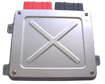