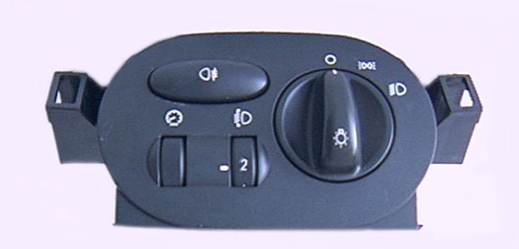
LIGHT SWITCH MODULE V28 - System Overview
The LSM controls and regulates all external lights including trailer lights if one is attached. It can adjust settings such as headlight position beam position and so on. This system only covers coding index 28.
SM082 - LIGHT SWITCH MODULE V28 - System Help file
Version 1.22

LIGHT SWITCH MODULE v28 - Known Fitments
Vehicle makes, models and variants known or believed to be using this vehicle system, required diagnostic lead and degree of known compatibility.

Vehicle Make Vehicle Model Vehicle Variant Diagnostic Lead
Rover 75 All Models Black OBDII Lead
Rover 75 Tourer All Models Black OBDII Lead
MG ZT All Models Black OBDII Lead
MG ZTT All Models Black OBDII Lead

LIGHT SWITCH MODULE v28 - Physical Details


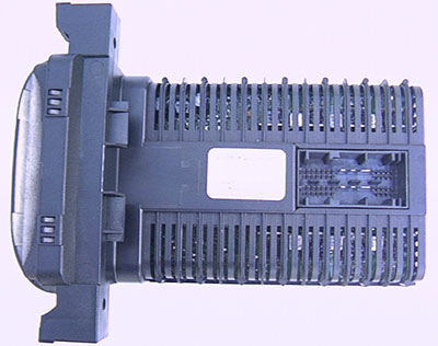
LIGHT SWITCH MODULE v28 - Pin Outs
Details of the pin usage for the ECU connector(s).

 
1 LH rear direction indicator
2 Not used
3 RH side repeater
4 Not used
5 LH stop lamp
6 VBatt 12V supply
7 LH dipped beam
8 RH main beam
9 Trailer bus
10 RH stop lamp
11 RH front direction indicator
12 LH/RH direction indicator switch
13 Flash / Main beam switch
14 Not used
15 Ignition switch IGN supply signal
16 CHMSL
17 LH/RH number plate lamps
18 LH side repeater
19-20 Not used
21 K Bus
22 - 23 Not used
24 Hazard warning switch
25 Brake lamp switch
26 Not used
27 Ignition switch AUX supply signal
28 Front fog relay
29 RH tail lamp
30 LH tail lamp
31 Earth
32 Earth
33 VBatt 12V supply
34 RH dipped beam
35 LH main beam
36 Illumination dimmer
37 - 38 Not used
39 LH headlamp levelling stepper motor
40 LH headlamp levelling stepper motor
41 LH headlamp levelling stepper motor
42 LH headlamp levelling stepper motor
43 RH rear direction indicator
44 RH front side lamp
45 LH front side lamp
46 Not used
47 RH rear fog lamp
48 Hazard warning switch illumination
49 LH rear fog lamp
50 LH front direction indicator
51 RH headlamp levelling stepper motor
52 RH headlamp levelling stepper motor
53 RH headlamp levelling stepper motor
54 RH headlamp levelling stepper motor

SM082 - LIGHT SWITCH MODULE v28 - Diagnostic Capabilities (Read Fault Codes)
Reads the fault code memory. The system can self detect up to 63 different problems with itself and associated sensors, storing the respective code if it detects any malfunction or reading outside of pre defined acceptable limits. Not all stored faults may cause the fault warning lamp to illuminate.

SM082 - LIGHT SWITCH MODULE v28 - Diagnostic Capabilities (Clear Fault Codes)
Clears the fault code memory.

SM082 - LIGHT SWITCH MODULE v28 - Diagnostic Capabilities (Settings)
Values, configuration settings and other stored information which can be read from the ECU, edited and then rewritten back. Read settings can also be stored as a standard HTML page for reference. These pages can then later be re loaded and re written back to the ECU. Please note that some values may be read only due to the fact that they are supplied from the ECU’s ROM or are internally calculated.

This gives 3 choices, General settings and information, Read ECU data to Map file and Program ECU with data from map file.
The read ECU data to Map file and Program ECU with data from map file functions allow you to save data from any ECU as a MAP file and re use it at any time to re program any new or used ECU. The General settings and Information allows values, configuration settings and other stored information, to be read from the ECU, edited and then rewritten back. Read settings can also be stored as a standard HTML page for reference. These pages can then later be re loaded and re written back to the ECU. Please note that some values may be read only due to the fact that they are supplied from the ECU’s ROM or are internally calculated.

GENERAL SETTINGS AND INFORMATION
  • Part Number: This is the part number for the ECU.
  • Supplier Number: This is a number which defines the supplier using a standard look up list of supplier ECU manufacturer numbers.
  • Hardware Number: This is the hardware version which denotes the processor and circuit board type.
  • Software Number: This denotes the coding inside the processor for the hardware.
  • Manufacturing Week: Gives the week in which the unit was built.
  • Manufacturing Year: Gives the year in which the unit was built.
  • Mileage: Gives the total distance covered by vehicle.
  • VIN Number: Gives the car VIN number.
  • Coding Index: This is the coding identification for the programming maps.
  • Diagnostic Index: This is a number that indicates the diagnostic capabilities support level.
  • Bus Index: This is a number that indicates the bus communication support level, the vehicle communication buses.
READ ECU DATA TO MAP FILE
This function reads the entire memory of the ECUand it stores on the server in a file that starts with LSM.

PROGRAM ECU WITH DATA FROM MAP FILE
Clicking on this link causes the vehicle explorer to communicate with the Vehicle Server to obtain a list of all of the map files on the vehicle server which can be programmed into the ECU. It will then automatically open the following page:
  • PROGRAM SELECTED MAP TO ECU
    You must program a valid ECU map. To program a map, select, from the drop down menu, the map that you want to use to program into the ECU and then click on the button itself around the list box. The Vehicle Server will start programming the ECU and give you a status report of progress as it does so. The system automatically verifies that they are maps for the Instrument pack type 3 ECU and suitable for the ECU's coding index.


SM082 - LIGHT SWITCH MODULE v28 - Diagnostic Capabilities (Inputs)
Constantly updating display in HTML of real time information the electronic control unit of the selected vehicle system is currently deriving from its input sensors and switches. These displays can be saved as HTML snap shots, recorded as an AVI movie or captured as A CSV data file for import into a spread sheet program such as Excel.

  • Right high beam: Gives the state of the front right high beam lamp.
  • Left high beam: Gives the state of the front left high beam lamp.
  • Right low beam: Gives the state of the front right low beam lamp.
  • Left low beam: Gives the state of the front left low beam lamp.
  • Right front indicator light: Gives the state of the right front indicator.
  • Left front indicator light: Gives the state of the left front indicator.
  • Right sidelight: Gives the state of the front right side light.
  • Left sidelight: Gives the state of the front left side light.
  • Right break light: Gives the state of the right brake light.
  • Left break light: Gives the state of the left brake light.
  • Left tail light: Gives the state of the left rear tail light.
  • Right tail light: Gives the state of the right rear tail light.
  • Left rear fog lamp: Gives the state of the left rear fog light.
  • Right rear fog lamp: Gives the state of the right rear fog light.
  • Right rear indicator: Gives the state of the right rear and side indicators.
  • Left rear indicator: Gives the state of the left rear and side indicators.
  • Number plate lamp: Gives the state of the Licence Plate light.
  • Centre break lamp: Gives the state of the rear high level brake light.
  • Head light aim: Gives the state of the front headlight aim.
  • Hazard lamps: Displays the state of the hazard lights.
  • Trailer right tail light: Gives the state of the right tail light for the trailer.
  • Trailer left tail light: Gives the state of the left tail light for the trailer.
  • Trailer right indicator: Gives the state of the right indicator for the trailer.
  • Trailer left indicator: Gives the state of the left indicator for the trailer.
  • Front fog lights: Gives the state of the front fog lights.
  • Trailer fog/reverse lights: Gives the state of the fog / reverse light for the trailer.
  • Trailer brake lights: Displays the state of the brake lights for the trailer.

SM082 - LIGHT SWITCH MODULE v28 - Diagnostic Capabilities (Outputs)
Choice of outputs that can be tested. The outputs would be pulsed.
  • Left Sidelight: The front left side light can be switched ON and OFF.
  • Right Sidelight: The front right side light can be switched ON and OFF.
  • Left High Beam: The front left high beam headlight can be switched ON and OFF.
  • Right High Beam: The front right high beam headlight can be switched ON and OFF.
  • Left Low Beam: The front left low beam headlight can be switched ON and OFF.
  • Right Low Beam: The front right low beam headlight can be switched ON and OFF.
  • Number Plate Light: The number plate light can be switched ON and OFF.
  • Left Rear Tail Light: The left rear tail light can be switched ON and OFF.
  • Right Rear Tail Light: The right rear tail light can be switched ON and OFF.
  • Left Rear Brake Light: The left rear stop light can be switched ON and OFF.
  • Right Rear Brake Light: The right rear tail light can be switched ON and OFF.
  • Right High Level Brake Light: The centre rear stop light can be switched ON and OFF.
  • Front Left Indicator Light: The front left indicator can be switched ON and OFF.
  • Front Right Indicator Light: The front right indicator can be switched ON and OFF.
  • Left Rear and Side Indicator Light: The left rear indicator and side repeater can be switched ON and OFF.
  • Right Rear and Side Indicator Light: The right rear indicator and side repeater can be switched ON and OFF.
  • Hazard Lights: The hazard lights can be turned ON and OFF. This signal changes the state of the hazard lights so has four states, No change, ON, No change, OFF, No change.
  • Front Fog Light: Front fog light can be switched ON and OFF.
  • Rear Left Fog Light: The back left fog light can be switched ON and OFF.
  • Rear Right Fog Light: The back right fog light can be switched ON and OFF.
  • Headlamp Position: Headlamp position can be set to UP or DOWN.
  • Hazards: Hazard lights can be forced to ON, LEAVE HAZARDS ON, OFF, LEAVE HAZARDS OFF.