ATC (ROVER 75) - System Overview
This dashboard mounted unit is custom manufactured by Nippon Denso for this application. An intelligent control module regulates climate control taking into account and compensating for factors such as solar radiation and vehicle speed. This is achieved though various temperature/speed sensors, flap motors, blower motors and air conditioning, working collectively to achieve stable internal temperatures.
SM083 - ATC (ROVER 75) - System Help file
Version 1.22

ATC (ROVER 75) - Known Fitments
Vehicle makes, models and variants known or believed to be using this vehicle system, required diagnostic lead and degree of known compatibility.

Vehicle Make Vehicle Model Vehicle Variant Diagnostic Lead
Rover 75 All Models Black OBDII Lead
Rover 75 Tourer All Models Black OBDII Lead
MG ZT All Models Black OBDII Lead
MG ZTT All Models Black OBDII Lead

ATC (ROVER 75) - Physical Details

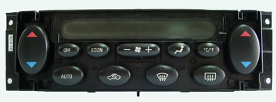
ATC (ROVER 75) - Pin Outs
Details of the pin usage for the ECU connector(s).

 
1 RH blend flaps servo motor, drive to hot
2 LH blend flaps servo motor, drive to hot
3 Distribution flap servo motor, drive to windscreen and side windows
4 RH blend flaps position
5 LH blend flaps position
6 Distribution flap position
7 Heater coolant temperature
8 Evaporator temperature
9 In-car air temperature
10 Sensor power supply
11 RH blend flaps servo motor, drive to cold
12 LH blend flaps servo motor, drive to cold
13 Distribution flap servo motor, drive to face
14 Blower control
15 Blower feedback
16 Blower relay
17 Not used
18 LH solar heating load
19 RH solar heating load
20 Sensor earth

 
1 Battery power supply
2 Ignition power supply Input
3 Auxiliary power supply
4 Earth
5 Illumination dimming
7 K bus
8 Side lamp/headlamp status
9 Hand of drive

SM083 - ATC (ROVER 75) - Diagnostic Capabilities (Read Fault Codes)
Reads the fault code memory. The system can self detect up to 8 different problems with itself and associated sensors, storing the respective code if it detects any malfunction or reading outside of pre defined acceptable limits. Not all stored faults may cause the fault warning lamp to illuminate.

SM083 - ATC (ROVER 75) - Diagnostic Capabilities (Clear Fault Codes)
Clears the fault code memory.

SM083 - ATC (ROVER 75) - Diagnostic Capabilities (Settings)
Values, configuration settings and other stored information which can be read from the ECU, edited and then rewritten back. Read settings can also be stored as a standard HTML page for reference. These pages can then later be re loaded and re written back to the ECU. Please note that some values may be read only due to the fact that they are supplied from the ECU’s ROM or are internally calculated.

  • Software Number: This denotes the coding inside the processor for the hardware.
  • Supplier Number: This is a number which defines the supplier using a standard look up list of supplier ECU manufacturer numbers.
  • Drive: This shows whether the car is right hand or left hand drive.

SM083 - ATC (ROVER 75) - Diagnostic Capabilities (Inputs)
Constantly updating display in HTML of real time information the electronic control unit of the selected vehicle system is currently deriving from its input sensors and switches. These displays can be saved as HTML snap shots, recorded as an AVI movie or captured as A CSV data file for import into a spread sheet program such as Excel.

  • ATC System: Gives the state of the ATC controller. The engine must be running. The ATC system is switched on and off by the “off” button. The “ECON” button also switches ATC off.
  • A/C Compressor: Gives the state of the A/C compressor. Engine must be running higher than 500rpm. Make ATC settings are set for maximum cooling. The compressor can be turned on or off using the ECON button. The ECON button also switches ATC off.
  • Recirculation: Gives the state of the ATC controller recirculation input. Make sure that ATC is on. This input can be changed with the recirculation button.
  • In Car Temperature: Gives the in car temperature value in C.
  • Evap Temperature: Gives the evaporator temperature value in C. Values are normally between -1C and +1C, whilst in operation.
  • Water Temperature: Gives the heater water temperature input value in C. Value is normally around 80C whilst the engine is at normal operating temperature.
  • Ambient Temperature: Gives the ambient temperature value sent to the ATC by the Instrument Pack ECU in C.
  • Vehicle Speed: Gives the vehicle speed as sent to the ATC by the instrument pack ECU. Between 96kph and 144kph the blower gradually reduces by up to 4 levels to allow for the increased air flow caused by the vehicles speed.
  • Blower Level: Gives the blower level output value. Make sure that ATC is on. The ATC controls the blower with a range of 31 steps, 0 representing off and 31 representing fully on. This value can be altered using the blower "+" and "-" buttons, which will increase or decrease the steps in increments of 6. Typically manual control levels are 3, 8,14,19,25 and 31. Between 96kph and 144kph the blower will gradually back off by up to 4 levels to compensate for the increased air flow due to the vehicle speed.
  • Left Solar: Gives the ATC input value from the left solar sensor. To balance out heating caused by solar radiation additional cooling is provided. This value may be altered using a torch to simulate light on the sensor but will return a fault if the light level is too low.
  • Right Solar: Gives the ATC input value from the left solar sensor. To balance out heating caused by solar radiation additional cooling is provided. This value may be altered using a torch to simulate light on the sensor but will return a fault if the light level is too low.
  • Target Air Distribution: Gives ATC controller target air distribution as a percentage. The actual air distribution should reach this value by +/-10%, 0% and 100% representing “FACE” and “DEFROST” respectively. Set the blower to maximum and turn ATC on. Pressing the “Air Distribution” button will change the value an observable amount.
  • Actual Air Distribution: Gives ATC controller actual air distribution as a percentage. Normally within +/-10% of the target air distribution, where 0% and 100% represent “FACE” and “DEFROST” respectively. The potentiometer belonging to the air distribution servo will provide the actual air distribution. Set the blower to maximum and turn ATC on. Pressing the “Air Distribution” button will change the value an observable amount.
  • Target Passenger Blend: Gives the passengers side ATC target air blend flap position as a percentage. The potentiometer gives the real air blend position which should not vary from this value by more than 10%. Values of 0% and 100%, representing cold and hot respectively. Make sure that ATC is on, the blower has air distribution set to “face”, and is operating at maximum. Also ensure engine is running higher than 500rpm and has reached normal temperature. Pressing the temperature control button on the passenger’s side will change the value an observable amount.
  • Target Driver Blend: Gives the drivers side ATC target air blend flap position as percentage. The potentiometer gives the real air blend position which should not vary from this value by more than 10%. Values of 0% and 100%, representing cold and hot respectively. Make sure that ATC is on, the blower has air distribution set to “face”, and is operating at maximum. Also ensure engine is running higher than 500rpm and has reached normal temperature. Pressing the temperature control button on the driver’s side will change the value an observable amount.
  • Blend Left Pot: Gives the left air blend potentiometer ATC input value as a percentage. This should not differ from the target value by more than 10%. Values of 0% and 100%, representing COLD and HOT respectively. Make sure that ATC is on, the blower has air distribution set to “face”, and is operating at maximum. Also ensure engine is running higher than 500rpm and has reached normal temperature. Pressing the temperature control button on the left side will change the value an observable amount.
  • Blend Right Pot: Gives the right air blend potentiometer ATC input value as a percentage. This should not differ from the target value by more than 10%. Values of 0% and 100%, representing COLD and HOT respectively. Make sure that ATC is on, the blower has air distribution set to “face”, and is operating at maximum. Also ensure engine is running higher than 500rpm and has reached normal temperature. Pressing the temperature control button on the right side will change the value an observable amount.

SM083 - ATC (ROVER 75) - Diagnostic Capabilities (Outputs)
Choice of outputs that can be tested.

  • In Car Temperature: Forcing this output changes the in car temperature output value. Three available output options of -10C, 30C, 60C. In order to feel the air the air compressor must also be forced simultaneously.
  • Ambient Temperature: Forcing this output changes the ambient temperature output value. Two available output options -10C , 55C. In order to feel the air the air compressor must also be forced simultaneously.
  • Evaporator Temperature: Forcing this output changes the evaporator temperature output value. Two available output options -5C , 5C. In order to feel the air the air compressor must also be forced simultaneously.
  • Water Temperature: Forcing this output changes the water temperature output value. Two available output options -10C, 80C.
  • Left Solar Radiation: Forcing this output changes the left solar radiation output value. Two available options 0 kw/m2, 1 kw/m2. To balance out heating caused by solar radiation additional cooling is provided.
  • Right Solar Radiation: Forcing this output changes the left solar radiation output value. Two available options 0 kw/m2, 1 kw/m2. To balance out heating caused by solar radiation additional cooling is provided.
  • Vehicle Speed: Forcing this output changes vehicle speed output value. Between 96kph and 144kph the blower gradually reduces by up to 4 levels to allow for the increased air flow caused by the vehicles speed.
  • Left Air Blend: Forcing this output changes the left air blend output value. Two available output options of “Cold” and “Hot”, representing 0% and 100% respectively. In order to feel the air the air compressor must also be forced simultaneously.
  • Right Air Blend: Forcing this output changes the right air blend output value. Two available output options of “Cold” and “Hot”, representing 0% and 100% respectively. In order to feel the air the air compressor must also be forced simultaneously.
  • Air Distribution Flap: Forcing this output changes the air distribution flap output value. Two output options are available, “Face” and “Screen”. In order to feel the air the air compressor must also be forced simultaneously.
  • Air Compressor: Forcing this output changes the air compressor output value. Two available options. Compressor “On” and “Off”.
  • Air Circulation: Forcing this output changes the air circulation output value. Two available options, “Fresh” and “ Recirculate ”.
  • Heated Rear Window: Forcing this output changes the heated rear window output state “On” and “Off”.
  • Blower Level: Forcing this output changes the blower level output value. Seven output options available, 0%, 15%, 25%, 50%, 75%, 85% and 100%. In order to feel the air the air compressor must also be forced simultaneously.

SM083 - ATC (ROVER 75) - Diagnostic Capabilities (Other)
Choice of functions that can be performed.

  • Air Distribution Servo Test: Test will send air distribution servos to certain position, defines as a percentage. ECU will read back actual position of servo for comparison.
  • Left Blend Servo: Test will send left blend servo to certain positions, defined as a percentage. ECU will read back actual position of servo for comparison.
  • Right Blend Servo: Test will send right blend servo to certain positions, defined as a percentage. ECU will read back actual position of servo for comparison.
  • Recirculation Test: Tests the “Fresh” and “Recirculation” of the ATC. In order to feel the air the air compressor must also be forced simultaneously.