SM096 - EDC15M (ROVER) - System Help file
Version 1.22

EDC15M - Known Fitments
Vehicle makes, models and variants known or believed to be using this vehicle system, required diagnostic lead and degree of known compatibility.

Vehicle Make Vehicle Model Vehicle Variant Diagnostic Lead
Rover 25 All diesels Black OBDII lead
Rover 45 All diesels Black OBDII lead
Rover Streetwise All diesels Black OBDII lead
Rover ZR All diesels Black OBDII lead
Rover ZS All diesels Black OBDII lead
Rover Express All diesels Black OBDII lead

EDC15M - Physical Details

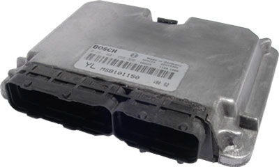
SM096 - EDC15M - Diagnostic Capabilities (Read Fault Codes)
Reads the fault code memory. The ECU can self detect around 88 different problems with itself, its wiring and its associated sensors, storing the respective code if it detects any malfunction or reading outside of predefined acceptable limits. Not all stored faults may cause the fault warning lamp to illuminate.

SM096 - EDC15M - Diagnostic Capabilities (Clear Fault Codes)
This function clears the fault code memory. Failure to clear the fault memory successfully is usually due to the system relogging the fault the moment the fault memory is clear. This indicates that the fault has not been rectified properly and as far as the system is concerned, still exists. The recheck for successful clearing of the fault code memory may be successfully executed but then the system may relog the fault shortly after.

SM096 - EDC15M - Diagnostic Capabilities (Settings)
Values, configuration settings, and other stored information which can be read from the ECU, edited and then rewritten back. Read settings can also be stored as a standard HTML page for reference. These pages can then later be reloaded and rewritten back to the ECU. Please note that some values may be read only due to the fact that they are supplied from the ECU's ROM or are internally calculated.

  • Date of build: This is the date the ECU was manufactured.
  • Software number: This denotes the coding inside the processor for the hardware.
  • Part Number: This is the Siemens part number for this ECU.
  • VIN: This is the vehicle identification number.
  • Assembly number: This is a unique number which defines the ECU hardware and software combination.
  • Programming date: This is the date in day/month/year that the Engine Management was last programmed.
  • Coding Index: The coding index for this ECU.
  • Diagnostic Index: The diagnostic index for this ECU.
  • Bus Index: The bus index for this ECU.
  • Idle speed:
  • GM Code: This is a unique code that identifies the configuration of the vehicle. It is stored in several ECUs within the vehicle and allows the manufacturer to uniquely identify each and every possible option for the vehicle. It is used in conjunction with the SA Code and the VN Code. The function to decode these into their meanings and to create a code from options is in the "Other Systems" section under the main menu of Freelander. The code is formatted by 8 hex numbers.
  • SA Code: This is a unique code that identifies the configuration of the vehicle. It is stored in several ECUs within the vehicle and allows the manufacturer to uniquely identify each and every possible option for the vehicle. It is used in conjunction with the GM Code and the VN Code. The function to decode these into their meanings and to create a code from options is in the "Other Systems" section under the main menu of Freelander. The code is formatted by 8 hex numbers.
  • VN Code: This is a unique code that identifies the configuration of the vehicle. It is stored in several ECUs within the vehicle and allows the manufacturer to uniquely identify each and every possible option for the vehicle. It is used in conjunction with the SA Code and the GM Code. The function to decode these into their meanings and to create a code from options is in the "Other Systems" section under the main menu of Freelander. The code is formatted by 5 hex numbers.
PROGRAMMING RECORDS (Flash type ECUs only)
The ECU has an area of memory allocated for programming history records. Each record, which is a fixed length contains the VIN number, programming date, assembly number, Homologation number and some unused hexadecimal data. Whenever a new record is added, it is placed after the last record and then becomes the active record which diagnostic equipment such as TestBook reads to obtain information about what an ECU is currently programmed with to see if there are any updates required to be programmed into it. It also uses the absence of any records to indicate a new ECU, which is the only time it allows a vehicle configuration change as from then on it uses the last Assembly number to dictate the maps uses to update the ECU with. It does not appear to verify that the actual maps in the ECU are those indicated by the Assembly number shown in the last / Active programming record, or read previous records. It is not diagnostically possible to erase or modify existing programming records. The possible space is limited before the ECU can no longer be updated and must be replaced, which ultimately results in additional ECU sales. It is therefore likely that the ECU may well not accept the programming of all possible spaces.

The page shows the Active Record, which is the actually the last record, is then shown under that and is provided here as a duplicate of the last record simply to save having to scroll to the bottom of a possibly long list to get to the last record and the used Programming Records from 1 to the last one used.
  • VIN number: This is the vehicle's VIN number and it can be programmed only when an ECU is reprogrammed by a Test Book.
  • Programming date: This is the date the ECU was programmed.
  • Assembly number: This is the Assembly number.
  • Homolog. number: This is the recorded emission control test number (Homologation) which is allocated to the ECU configuration / fuel tune map set by the respective authority.
  • Programming station: This is the station used to program the ECU.
  • Odometer value: This is the odometer value at the programming time.
  • Unused data: Data that currently has no known usage but as something is required to be supplied when programming a new record, it has to be filled in. We suggest that you use the same data taken from the last programming record, which can be typed in manually or cut and pasted in using CTRL-C and CTRL-V key combinations.
  • Database Data: By clicking on this link, it will open a special database that allows you to see and browse all the known Assembly numbers and their respective information about them. The Database will open with the record highlighted for the Assembly number from the active / last programming record For more information on how to use this map database, see Map Database.

SM096 - EDC15M - Diagnostic Capabilities (Inputs)
Realtime live display of the information the electronic control unit of the selected vehicle system is currently deriving from its input sensors.

  • Vehicle Speed: This is the vehicle speed in kph and mph as measured by the gearbox. Failure of this input would disable surge damping and air conditioning, if fitted.
  • Engine Speed: This is the engine speed in rpm supplied by the crank sensor.
  • Secondary Engine Speed: This is the engine speed in rpm as measured by the injection pump. The engine speed is derived from the pump cam tonewheel signal.
  • Idle Speed Setpoint: This is the target engine speed in rpm. When the low idle switch is open, EDC15M ECU will adjust the fuelling to reach the idle speed setpoint. Typical values are 805 rpm or 850 rpm if air conditioning is operating.
  • Airflow: This shows the mass airflow into the engine. The value is used by the EGR control: as EGR increases the airflow reduces. At steady idle airflow will be between 250 and 400 mg/fire depending upon the amount of EGR applied. EGR control is turned off after one minute at steady idle speed.
  • EGR Target Airflow: This shows the target fresh airflow into the engine (when idle control is active) and is used by the EGR Control to adjust the amount of recirculated exhaust gas. At steady idle speed EGR control is applied for one minute then turned off.
  • EGR Duty Ratio: This shows the open/close duty ratio of the EGR valve. This value is used to recirculate exhaust gases to reduce emissions and combustion noise. The higher the reading the more EGR. Failure of this modulator would lead to increased smoke emissions and combustion noise.
  • Start of Injection Setpoint: This shows the setpoint in crankshaft degrees calculated by the ECU for the start of fuel injection for cylinder 1. The setpoint is calculated using the driver demand and current engine conditions to determine from the engine map the required angle.
  • Start of Injection Actual: This shows the actual angle in crankshaft degrees determined by the ECU for the start of fuel injection for cylinder 1. The actual angle is determined from the needle lift sensor fitted to the injector in cylinder 1.
  • Demand Pedal Fuel Quantity: This shows the fuel quantity request determined by the ECU from the position of the driver demand potentiometer.
  • Current Fuel Quantity: This is the fuel quantity determined by the driver demand quantity checked against the limit maps, i.e. smoke, torque, etc. and the current engine conditions, i.e. temperatures, engine speed etc.
  • Pump Message Quantity: This is the actual fuel quantity to be injected. This is determined by the current fuel quantity adjusted for cylinder balancing, surge damping and pump based nozzle corrections.
  • Limit Fuel Quantity: This is the maximum fuel quantity permitted based on the current engine conditions. This is determined by the driver demand request, current fuel quantity and fuel map.
  • Smoke Limit Fuel Quantity: This is the maximum fuel quantity permitted to prevent excessive smoke.
  • Idle Governor Fuel Quantity: This is the fuel quantity used to achieve idle control.
  • Demand Pedal Sensor Supply: This is the regulated supply voltage for the demand pedal sensor.
  • Boost Pressure Sensor Supply: This shows the regulated supply voltage for the boost pressure sensor.
  • Airflow Sensor Supply: This shows the regulated supply voltage for the airflow sensor.
  • A/C Evaporator Temperature: This is the temperature measured by the ECU using the temperature sensor in the air conditioning evaporator. This value is used to determine when to turn off the compressor to prevent freezing the refrigerant.
  • A/C Switch: This displays the state of the air conditioning switch on the dashboard.
  • Actual Fan Speed: This displays the cooling fans speed: OFF - cooling fans are not running, SLOW - cooling fans are being run in series, FAST - cooling fans are being run in parallel. The ECU determines the fan speed dependant upon coolant temperatures, A/C state and current driving conditions. The cooling fans serve the dual purpose of cooling both the engine coolant and air conditioning refrigerant.
  • Requested Fan Speed: This displays the state of the cooling fan speed requested by the air conditioning system. OFF - cooling fans not requested by the A/C, SLOW - whenever air conditioning is active, unless system pressure increases above a preset threshold in which case FAST mode is requested. The cooling fans serve the dual purpose of cooling both the engine coolant and air conditioning refrigerant.
  • A/C Compressor: This displays the state of the air conditioning compressor output drive.
  • A/C System Pressure: Shows the air conditioning system pressure as measured by the ECU using the sensor mounted inside the air drier. Failure of the sensor will disable the air conditioning system and raise a fault flag.
  • Glow Plug Lamp: This shows the state of the glowplug lamp drive output.
  • Diagnostic Lamp: This displays the state of the diagnostic lamp output drive.
  • Glow Plug Relay: This shows the state of the glowplug relay drive output.
  • Brake: This displays the state of the footbrake pedal brake switch as seen by the ECU.
  • Low Idle Switch: This shows the state of the idle switch which is part of the driver demand potentiometer. The idle switch will open if the pedal rotation is below 9%. In this conditions, the ECU will adjust fuelling to achieve the required idle speed. Once the idle switch closed, fuelling is proportional to pedal position.
  • Coolant Temperature: This shows the coolant temperature as measured by the ECU. Sensor faults may cause several symptoms including poor starting, fast idle speed, poor fuel consumption and cooling fan running continuously. Typical value with a fully warm engine is 88C;°.
  • Inlet Air Temperature C: This shows the temperature measured by the ECU using the inlet air temperature sensor. This is used by the ECU to adjust the ignition timing at altitude. If the sensor is not operating correctly poor EGR and smoke control could result.
  • Fuel Temperature C: This shows the temperature measured by the ECM using the temperature sensor in the injection pump. If the sensor is open circuit then a fixed default value will be displayed. The fuel temperature is used by the ECM as an aid to hot starting and to make corrections to fuelling. If the sensor is not operating correctly hot starting and engine performance may be impaired slightly. Typical value with a fully warm engine is 78C;°.
  • Battery voltage: Displays the battery voltage as measured by the ECU.
  • A/C Idle Speed Setpoint: This shows the target engine speed in rpm that the ECU will adjust fuelling for when air conditioning is active and the low idle switch is open, typically 850 rpm.
  • Demand Pedal Rotation: This shows the percentage rotation of the driver demand potentiometer as read by the ECU.
  • Demand Pedal Output: This shows the output voltage of the driver demand potentiometer as read by the ECU. The voltage reading increases as the throttle pedal is depressed. With the pedal released the value should be 0.3 - 0.6 Volts and fully depressed 3.3 - 3.7 Volts.
  • Ambient Pressure: Shows the ambient atmospheric pressure as measured by the sensor mounted inside the ECU. This is used to adjust the timing at altitude. Typical values are approx. 100kPa at sea level, dropping with altitude to the region of 80kPa at 2000 metres.
  • Manifold Pressure: Shows the pressure measured by the pressure sensor mounted into the air intake manifold. Failure of the sensor will result in a default value of 100 Kpa being used. Typical values approx. 100 KPa at sea level with the engine stopped. Between 80 - 125 KPa during engine idle conditions. High values of up to 260 KPa may indicate when turbo boost is generated at around 3000 RPM.

SM096 - EDC15M - Diagnostic Capabilities (Outputs)
  • A/C compressor: This output forces the compressor ON or OFF for 10 seconds.
  • Glowplug: This output forces ON or OFF the power to the glowplug.
  • Cooling fan slow: This output forces ON or OFF the cooling fan slow.
  • Cooling fan fast: This output forces ON or OFF the cooling fan slow.
  • EGR vacuum modulator: This output forces ON or OFF the EGR vacuum modulator.
  • Diagnostic lamp: Turns ON or OFF the diagnostic lamp.

SM096 - EDC15M - Diagnostic Capabilities (Other)
Choice of functions that can be performed:
  • Read security status: The EDC15M ECU has much improved capabilities in terms of allowing diagnostic checking of the current status of the security link connection from the Alarm ECU. This function obtains the status of the link.
  • Security learn mode: This function instructs the ECU to learn the security code from alarm ECU.